
TS_619_00 PW9000DPA S2 User Manual 13/3/17
25
3: Installation
3.3
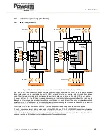
Installation planning (environmental & mechanical)
3.3.1 Environmental considerations
A certain amount of pre-planning will help provide a trouble-free installation process. You should consider the following
guidelines when planning a suitable UPS location and operating environment.
1. The route to the installation location must allow the equipment to be transported in an upright position.
2. The floor at the proposed installation site and en-route from the off-loading point must be able to safely support the
weight of the UPS and battery equipment, plus fork lift or trolley jack during transit.
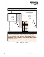
3. The UPS cabinet requires space to bottom/front, top and back to enable cooling airflow (see below).
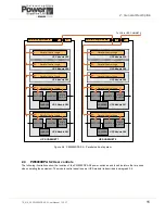
4. A minimum clearance of 200mm must be provided at the back of the cabinet to provide adequate ventilation. A
clearance of 400mm should also be provided at the top of the cabinet if the passage of cooling airflow at the back of
the cabinet is insufficient to dissipate the generated heat – see figure 3.1.
5. All parts of the UPS required for maintenance, servicing and user operation are accessible from the front of the
cabinet and require a minimum front clearance of 1000mm.
Note: The cabinet door must be opened by 115° in order to remove/fit the UPS modules, so the right-hand side of the
cabinet cannot be positioned directly against a projecting wall – see figures 3.1.
6. An ambient temperature of 20°C is necessary to achieve the recommended battery life span. The cooling air entering
the UPS modules must not 40°C.
7. The floor material should be non-flammable and strong enough to support the heavy load.
8. In summary, the UPS should be located where:
a) Humidity (< 90%) and temperature is ideally 20°C.
b) Fire protection standards are respected.
c) Cabling can be performed easily.
d) A minimum 1000mm front accessibility is available for service or periodic maintenance.
e) Adequate cooling air flow is available.
f)
The air conditioning system can provide a sufficient amount of air cooling to keep the room at, or below, the
maximum desired temperature.
g) No dust or corrosive/explosive gases are present.
h) The location is vibration free.
i)
If the UPS will be installed in bayed enclosures, partition walls must be installed.
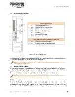
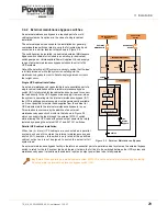
3.3.2 Clearances
Cooling air enters the front and bottom of the UPS cabinet and is extracted by ventilation fans mounted on the cabinet
rear. If the UPS cabinet is installed immediately adjacent to another cabinet, battery enclosure or wall, a minimum
clearance of 300mm is required at the rear of the cabinet to permit sufficient cooling air flow. This can be reduced to
200mm if the cabinet is installed as a stand-alone unit with at least 400mm combined side clearance (see Figure 3.1)
.
The UPS cabinet does not require any side clearance for ventilation or service access, so it can be installed immediately
alongside other UPS cabinets or battery cabinets to form an equipment suite. If an external battery cabinet is used you
should install it as close as possible to the UPS cabinet, ideally immediately adjacent to it.
If you install the recommended external battery cabinet or battery rack supplied by Uninterruptible Power Supplies Ltd. the
battery cabinet itself does not require any side or rear clearance.
All UPS cabling, maintenance and servicing procedures can be carried out from the front of the cabinet, and a front
clearance of at least 1000mm should be provided to enable component replacement.
Key Point:
When installing the UPS cabinet next to an external battery cabinet or battery rack, the battery
cabinet/rack might require more than 1000mm front clearance which must be taken into consideration when
installing a cabinet suite.
Key Point:
The UPS door must be fully opened (to approximately 115°) to enable some major component to be
extracted from the cabinet. If the right side of the cabinet is positioned against a wall that protrudes in front of the
cabinet you must allow adequate, additional side clearance. See the clearance diagrams above for details.
Содержание PowerWave 9000DPA S2
Страница 1: ...PowerWAVE 9000DPA S2 30 250 kVA User Manual ...
Страница 2: ...TS_619_00 PW9000DPA S2 User Manual 13 3 17 ...
Страница 8: ... IV TS_619_00 PW9000DPA S2 User Manual 13 3 17 ...