

52
TS_619_00 PW9000DPA S2 User Manual 13/3/17
7
Options
7.1
Introduction
The PW9000DPA S2 UPS system offers a range of monitoring and control interfaces that can be connected to external
facilities management systems. Depending on the system configuration, these interfaces can be applied at ‘UPS module’,
‘cabinet’ or ‘system’ level.
Interfacing at UPS module level
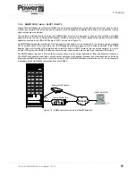
A ‘Smart Port’ connector (JD-1), fitted to the front of each power module, provides an intelligent RS232 serial port which
allows an individual UPS module to be connected to a PC and monitored by suitable software. This is a standard D-type,
9-pin connector with cable connection details shown in Figure 7.4.
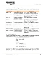
Interfacing at ‘cabinet’ or ‘system’ level
A customer interface board, which is fitted to the lower right of each UPS cabinet, provides various means of connecting
‘cabinet’ and ‘system’ level UPS monitoring and control interfaces to external devices. – see figure 7.1
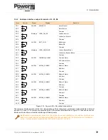
Figure 7.1 Customer interface board
Key Point:
If the UPS is operating as a parallel cabinet system and the ‘Multidrop’ application is enabled, the
customer interface board I/O is disabled in the ‘slave’ cabinet(s) and the interface connections should be made
on the customer interface board fitted in the ‘master’ module only.
2
3
4
6
5
7
1
Customer Interface Board
1
X1
Customer inputs (terminal block)
2
X2-X4
Customer dry port output (terminal blocks)
3
JD11
RS232 PC interface (Sub D-9 Female)
4
JD12
RS232 Multidrop (Sub D-9 Male)
5
USB
PC Interface
6
SLOT 1
Slot for SNMP (CS141 adapter)
7
SLOT 2
Slot for optional Modem/Ethernet card
Содержание PowerWave 9000DPA S2
Страница 1: ...PowerWAVE 9000DPA S2 30 250 kVA User Manual ...
Страница 2: ...TS_619_00 PW9000DPA S2 User Manual 13 3 17 ...
Страница 8: ... IV TS_619_00 PW9000DPA S2 User Manual 13 3 17 ...