2: General Description
16
TS_619_00 PW9000DPA S2 User Manual 13/3/17
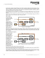
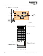
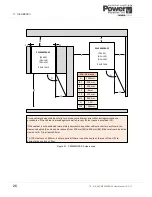
This facility requires a purpose designed ‘Multidrop’ cable to be connected between each module’s customer interface
board JD12.
Note that when the multidrop feature is used, the I/O facilities of customer interface board in the ‘slave’ cabinets are all
disabled, but the customer interface board fitted to the ‘master’ cabinet remains fully functional.
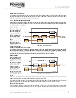
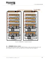
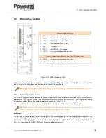
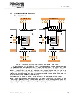
2.5.2 Parallel Interface Board
The parallel interface board facilitates the connection of the parallel control bus cables between the cabinets in a parallel
cabinet system. These cables are connected to a ‘Parallel Adapter’ board which is fitted to JD8.
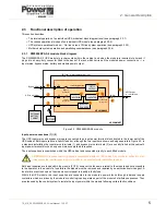
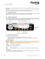
2.6
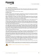
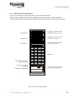
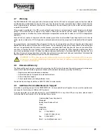
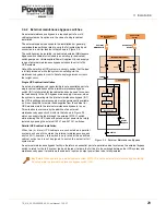
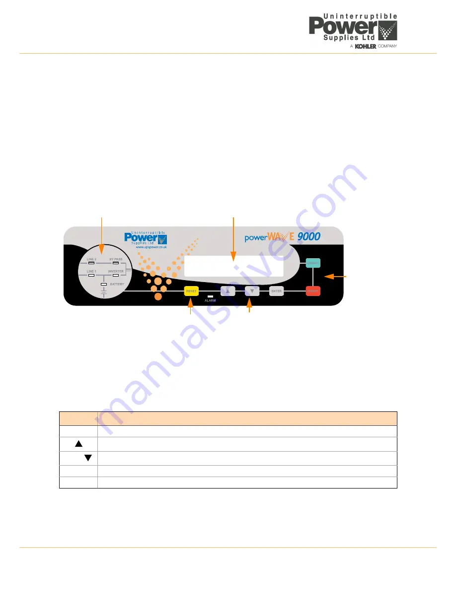
Module control panel
A door-mounted module control panel is provided for each UPS module. The control panel is used to start and stop the
module, command a load transfer between inverter and bypass, and monitor the module’s operating parameters. It is also
used to configure and interrogate the module during commissioning and troubleshooting.
Figure 2.13 Module control panel
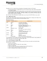
2.6.1 Module control panel buttons
The module control panel buttons allow you to:
• Start-up and shut down the UPS and transfer the load between inverter and bypass.
• Monitor and display the UPS operating voltages, currents, frequencies and other values on the LCD display.
• Reset/cancel an alarm.
Button function summary
ON/OFF Buttons
You can switch the UPS ON or OFF by simultaneously pressing both
ON/OFF
buttons (for less than 1s). The requirement
to press both buttons is to help prevent accidental operation.
BUTTON
FUNCTION
ON/OFF
Used to switch-on or switch-off the UPS by pressing both buttons simultaneously
UP
)
Scroll upwards through a displayed menu
DOWN
(
)
Scroll downwards through a displayed menu
ENTER
Selects a chosen menu item
RESET
Cancels an audible alarm. If the alarm condition is transient the
ALARM
LED will turn OFF, otherwise it will remain ON
Power Management Display (PMD)
Mimic LED Indicators
Menu navigation &
Alarm & Reset
selection buttons
Module ON/OFF
control buttons
Содержание PowerWave 9000DPA S2
Страница 1: ...PowerWAVE 9000DPA S2 30 250 kVA User Manual ...
Страница 2: ...TS_619_00 PW9000DPA S2 User Manual 13 3 17 ...
Страница 8: ... IV TS_619_00 PW9000DPA S2 User Manual 13 3 17 ...