


TS_619_00 PW9000DPA S2 User Manual 13/3/17
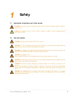
7
2: General Description
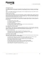
Inverter output contactor (10)
The inverter output contactor is driven by the UPS module’s control logic and operates in conjunction with the static switch
as part of the bypass/inverter load transfer process. The contactor is also used to isolate the inverter from the UPS output
within the module following certain overload or fault conditions.
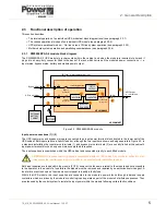
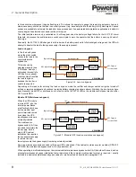
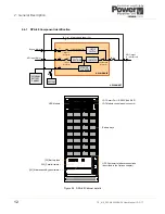
2.3.2 UPS Module operating modes
Simplified block diagrams are used in this section to illustrate the various UPS module operating modes. Note that where
two or more UPS modules are installed in a DPA-150 or DPA-250 cabinet they will always adopt the same operating mode
due to their parallel control signals.
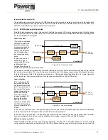
Load on inverter
This is the only operating
mode that provides the
load with continuously
processed and backed-
up power: and in the
majority of installations
can be considered as
the ‘normal’ operating
mode.
In this mode, the input
mains AC supply is
converted to DC by the
rectifier which then
charges the battery and
provides the operating power for the inverter.
The inverter converts the DC produced by the rectifier back to an AC power source which is then connected to the load via
the inverter output contactor. The inverter frequency is synchronised to the bypass supply provided the bypass frequency
remains within preset limits. If these limits are exceeded, or if the bypass supply fails altogether, the inverter frequency
control reverts to a free-running oscillator which produces a constant 50Hz or 60Hz UPS output.
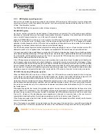
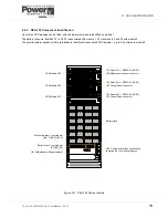
Load on battery
If the mains supply fails,
the rectifier shuts down
and the battery provides
the DC power source for
the inverter. The battery
voltage is regulated by
the booster circuit to
ensure the inverter
receives a suitable DC
input as the battery
discharges. On the
module control panel the
BATTERY
LED will flash
green to indicate that it is
on load.
In the case of a dual feed input
– if the bypass supply is still live when the input mains supply fails, the inverter frequency
remains synchronised to the bypass mains provided it is within its preset limits.
In the case of a single feed input
– the bypass supply will fail at the same time as the input mains supply and the inverter
frequency control reverts to its free-running oscillator and will provide a constant 50Hz or 60Hz UPS output.
Battery discharge operation
When the battery is placed on load, and begins to discharge, the
BATTERY
mimic LED flashes green on the module
control panel accompanied by an audible alarm. The LED continues flashing green until the remaining autonomy time falls
RECTIFIER
BATTERY
INVERTER
STATIC
SWITCH
BOOSTER /
CHARGER
INV. Output
Contactor
Bypass Mains
UPS MODULE
Static bypass line
UPS Input Mains
UPS Output
to critical load
Figure 2.4 Load on inverter
RECTIFIER
BATTERY
INVERTER
STATIC
SWITCH
BOOSTER /
CHARGER
INV. Output
Contactor
Bypass Mains
UPS MODULE
Static bypass line
UPS Input Mains
UPS Output
to critical load
Figure 2.5 Load on battery
Содержание PowerWave 9000DPA S2
Страница 1: ...PowerWAVE 9000DPA S2 30 250 kVA User Manual ...
Страница 2: ...TS_619_00 PW9000DPA S2 User Manual 13 3 17 ...
Страница 8: ... IV TS_619_00 PW9000DPA S2 User Manual 13 3 17 ...