


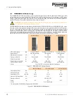
TS_619_00 PW9000DPA S2 User Manual 13/3/17
5
2: General Description
2.3
Functional description of operation
This section describes:
• The internal operation of an individual UPS module at block-diagram level (see paragraph 2.3.1)
• The various operational modes of an individual UPS module (see paragraph 2.3.2)
• UPS system operational modes – ‘On-line’ versus ‘Off-line’ system operation (see paragraph 2.3.3)
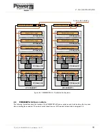
• Multi-module system operation and paralleling considerations (see paragraph 2.3.4)
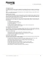
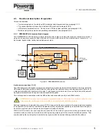
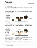
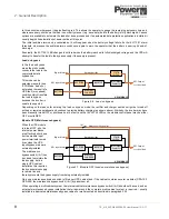
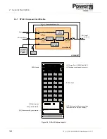
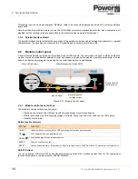
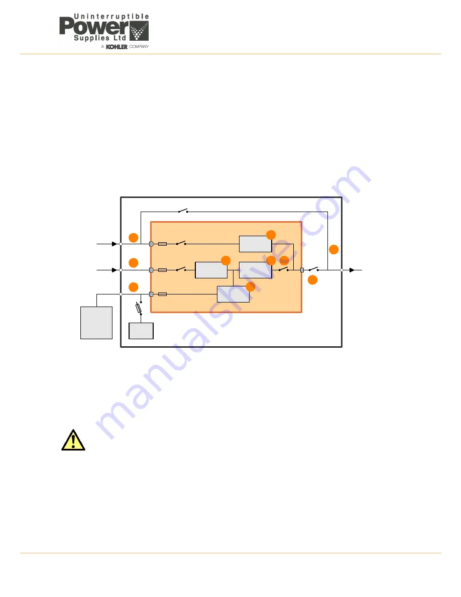
2.3.1 PW9000DPA S2 module block diagram
The PW9000DPA S2 UPS module is rack-mounted within the cabinet, and when the module is inserted into its rack it
plugs into a heavy-duty connector fitted to the back of the rack which carries all the module’s power connections – i.e.
input mains, bypass mains, battery and module power output.
Figure 2.3 PW9000DPA S2 module
Input power connections (1) / (2)
The UPS input mains and bypass mains are connected to an input power terminal block located in the lower part of the
UPS cabinet. Both inputs require a 3ph+N feed but, although the two inputs are shown as being separate in Figure 2.3, in
a standard installation the input mains terminals (1) and bypass mains terminals (2) are usually linked at the cabinet’s
input power terminal blocks so only one mains supply feed is required.
The input supplies are unswitched within the UPS cabinet and connected directly to each fitted module.
Both input supplies are fused within the module (F1/F2), however the fuses are internal to the module and not accessible
to the operator. In the event of a fuse failure the module must be removed and repaired by an authorised service agent. A
fuse failure event is shown on the module control panel to identify a faulty fuse.
Within the UPS module, the input supplies are connected to the module’s power blocks through individual supply
contactors which are driven by the module’s control logic and operate as part of the module’s start/stop sequences. They
are also used by the control system to isolate the input power within the module following certain fault conditions.
CAUTION: As the mains power supplies are unswitched within the UPS cabinet, the module(s) will be live at all
times unless the input/bypass supply is isolated at the external mains switchboard panel.
RECTIFIER
BATTERY
EXTERNAL
BATTERY
CABINET
INVERTER
STATIC
SWITCH
BOOSTER /
CHARGER
Bypass
Contactor
Inv. Output
Contactor
Input
Contactor
Bypass Mains
IA-2
IA-1
F4
F1
F2
F3
UPS MODULE
UPS CABINET
Static bypass line
Maintenance bypass line
UPS Input Mains
UPS Output
to critical load
3
4
1
2
5
6
7
8
9
10
Содержание PowerWave 9000DPA S2
Страница 1: ...PowerWAVE 9000DPA S2 30 250 kVA User Manual ...
Страница 2: ...TS_619_00 PW9000DPA S2 User Manual 13 3 17 ...
Страница 8: ... IV TS_619_00 PW9000DPA S2 User Manual 13 3 17 ...