

TS_619_00 PW9000DPA S2 User Manual 13/3/17
11
2: General Description
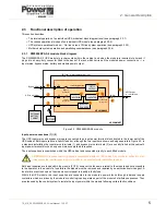
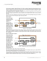
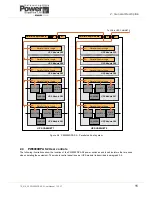
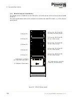
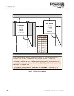
Figure 2.8 PW9000DPA S2 – Parallel cabinet system
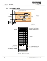
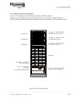
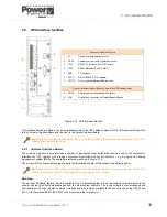
2.4
PW9000DPA S2 User controls
The following illustrations show the location of the PW9000DPA S2 power switches and fused isolators that are used
when operating the equipment. The module control panel (one per UPS module) is described in paragraph 2.6.
STATIC
SWITCH
INVERTER
RECTIFIER
Parallel Control Logic
UPS Module P06
CHARGER
STATIC
SWITCH
INVERTER
RECTIFIER
Parallel Control Logic
UPS Module P07
CHARGER
Parallel Control Logic
UPS Module P08
Parallel Control Logic
UPS Module P09
Parallel Control Logic
UPS Module P10
UPS CABINET 2
STATIC
SWITCH
INVERTER
RECTIFIER
Parallel Control Logic
UPS Module P01
CHARGER
STATIC
SWITCH
INVERTER
RECTIFIER
Parallel Control Logic
UPS Module P02
CHARGER
Parallel Control Logic
UPS Module P03
Parallel Control Logic
UPS Module P04
Parallel Control Logic
UPS Module P05
UPS CABINET 1
Parallel Adapter Board
To JD5 in UPS CABINET 3
JD5
JD6
Parallel Adapter Board
JD5
JD6
Содержание PowerWave 9000DPA S2
Страница 1: ...PowerWAVE 9000DPA S2 30 250 kVA User Manual ...
Страница 2: ...TS_619_00 PW9000DPA S2 User Manual 13 3 17 ...
Страница 8: ... IV TS_619_00 PW9000DPA S2 User Manual 13 3 17 ...