

TS_619_00 PW9000DPA S2 User Manual 13/3/17
53
7: Options
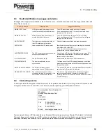
7.2
Customer interface board
The customer interface board connections include:
• Dry-port inputs for customer remote control options (X1) – see paragraph 3.6.1.
• Relay operated dry-port alarm outputs for remote monitoring (X2-X4) – see paragraph 3.6.2.
• RS232 computer interface for remote monitoring/control applications (JD11)
• RS232 computer interface for multidrop (JD12)
• USB port for computer monitoring applications
• An SNMP/CS141 card slot
• An SNMP slot for modem/Ethernet card
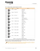
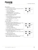
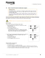
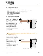
7.2.1 Remote shut down customer input
The remote shut down feature is enabled/
disabled via hardware code which is set during
commissioning. When it is enabled, the remote
shut down input is connected to a normally-
closed external contact which shuts down the
UPS when it is opened.
We recommend that a terminal block is
connected between the customer interface
board and the remote shut down switch, as
shown, so that the remote shut down contact
can be effectively linked-out to allow the
external circuit to be maintained or tested
without shutting down the UPS.
Connect the remote shut down device using a
screened cable with 1 pair (0.5 mm²) and
maximum length of 100m.
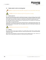
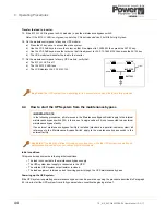
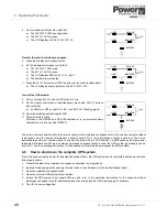
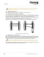
7.2.2 Generator ON customer input
The Generator ON input uses a normally-open
contact which closes when the standby
generator is running and supplying input power
to the UPS.
When used, this facility enables an option to
inhibit the battery charger and/or static
bypass. Use a screened cable with 1 pair
(section of wires 0.6 mm2) and maximum
length of 100 m.
In a parallel cabinet system only one ‘generator
ON’ input is required, connected to the
customer interface board in the master cabinet.
When the input is active it affects ALL the
cabinets in the system.
Key Point:
In a parallel cabinet system only one remote shut down switch is required, connected to the
customer interface board in the master cabinet. All the UPS cabinets will shut down when the remote emergency
shut down switch is operated.
1
2
3
4
5
6
7
8
9
10
X1
Customer Interface Board
Terminal
block
(link facility)
Remote
shutdown
contact (n/c)
Figure 7.2 Remote shut down cabling
1
2
3
4
5
6
7
8
9
10
X1
Customer Interface Board
Generator ON
switch contact (n/o)
Figure 7.3 Generator ON cabling
Содержание PowerWave 9000DPA S2
Страница 1: ...PowerWAVE 9000DPA S2 30 250 kVA User Manual ...
Страница 2: ...TS_619_00 PW9000DPA S2 User Manual 13 3 17 ...
Страница 8: ... IV TS_619_00 PW9000DPA S2 User Manual 13 3 17 ...