
T
S
_6
19_00 PW9000DPA S2 User Manual 13/3/17
35
3: Installation
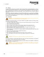
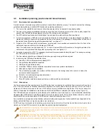
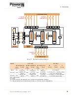
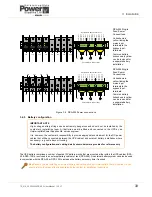
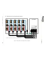
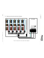
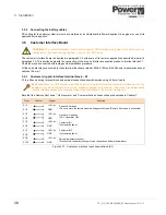
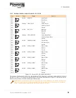
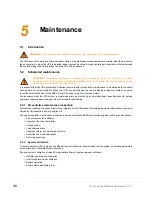
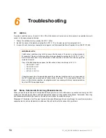
3.4.6 External battery enclosure with separate battery configuration
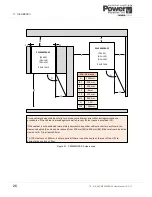
Figure 3.11 Wiring details for external separate battery configuration
PE
To UPS Modules’ Battery Connections
EXTERNAL BA
TTE
RY
ENCLOSURE
UPS CABINET
To
U
P
S
Modul
e
3
+
To
U
P
S
Modul
e
2
+
To
U
P
S
Modul
e
1
+
To
U
P
S
Modul
e
3
N
To
U
P
S
Modul
e
2
N
To
U
P
S
Modul
e
1
N
To
U
P
S
Modul
e
3
To
U
P
S
Modul
e
2
To
U
P
S
Modul
e
1
To
U
P
S
Modul
e
5
+
To
U
P
S
Modul
e
4
+
To
U
P
S
Modul
e
5
N
To
U
P
S
Modul
e
4
N
To
U
P
S
Modul
e
5
To
U
P
S
Modul
e
4
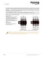
For reasons of clarity, the wiring for UPS modules 1,3,5 only is shown in detail
PE
01
String A
Fuses
Battery
String A
02
03
48
49
50
25
26
01
String B
Fuses
Battery
String B
02
03
48
49
50
25
26
01
String C
Fuses
Battery
String C
02
03
48
49
50
25
26
01
String D
Fuses
Battery
String D
02
03
48
49
50
25
26
01
String E
Fuses
Battery
String E
02
03
48
49
50
25
26
Содержание PowerWave 9000DPA S2
Страница 1: ...PowerWAVE 9000DPA S2 30 250 kVA User Manual ...
Страница 2: ...TS_619_00 PW9000DPA S2 User Manual 13 3 17 ...
Страница 8: ... IV TS_619_00 PW9000DPA S2 User Manual 13 3 17 ...