

TS_619_00 PW9000DPA S2 User Manual 13/3/17
39
3: Installation
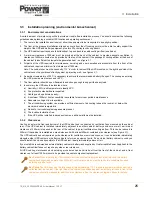
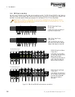
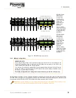
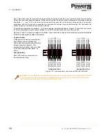
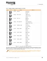
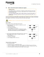
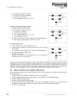
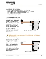
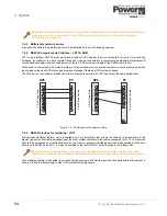
3.6.2 Customer interface output terminals – X2, X3, X4
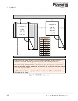
Figure 3.14 Dry port (X2– X4) output connections
The customer interface board contains ten relays whose volt-free changeover contacts are made available to terminal
blocks X2, X3, and X4. The relays are operated by the UPS status events identified in Figure 3.14, and can be used to
interface with most forms of remote monitoring and alarm panels.
Term
Contact
Signal
Display
Function
X2/1
ALARM
MAINS_OK
Mains Present
X2/2
Mains Failure
X2/3
Common
X2/4
Message
LOAD_ON_INV
Load on Inverter
X2/5
Load not on Inverter
X2/6
Common
X2/7
ALARM
BATT_LOW
Battery Low
X2/8
Battery OK
X2/9
Common
X2/10
Message
LOAD_ON_MAINS
Load on Bypass Mains
X3/1
Load not on Bypass Mains
X3/2
Common
X3/3
ALARM
COMMON_ALARM
Common Alarm
X3/4
No Common Alarm
X3/5
Common
X3/6
ALARM
MODUL_ALARM1
Module 1 Alarm
X3/7
No Alarm
X3/8
Common
X3/9
ALARM
MODUL_ALARM2
Module 2 Alarm
X3/10
No Alarm
X4/1
Common
X4/2
ALARM
MODUL_ALARM3
Module 3 Alarm
X4/3
No Alarm
X4/4
Common
X4/5
ALARM
MODUL_ALARM4
Module 4 Alarm
X4/6
No Alarm
X4/7
Common
X4/8
ALARM
MODUL_ALARM5
Module 5 Alarm
X4/9
No Alarm
X4/10
Common
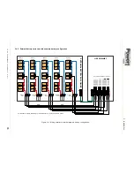
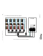
Key Point:
In a parallel cabinet system ALL the outputs shown are available from the customer interface board
fitted to the master cabinet. On those boards fitted to the slave cabinets only the ‘summary alarm’ outputs are
active – i.e those outputs connected from X3/3 to X3/10 and X4/1 to X4/10.
Содержание PowerWave 9000DPA S2
Страница 1: ...PowerWAVE 9000DPA S2 30 250 kVA User Manual ...
Страница 2: ...TS_619_00 PW9000DPA S2 User Manual 13 3 17 ...
Страница 8: ... IV TS_619_00 PW9000DPA S2 User Manual 13 3 17 ...