
TS_619_00 PW9000DPA S2 User Manual 13/3/17
29
3: Installation
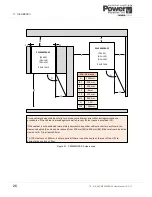
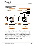
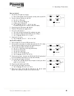
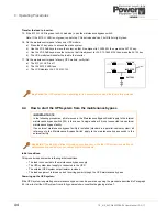
3.4.2 External maintenance bypass switches
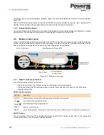
An external maintenance bypass is a required part of a multi-
cabinet system but is optional in the case of a single cabinet
installation.
The external bypass is bespoke to the installation but generally
comprises three switches rated to carry the full system load and
connected in a similar fashion to that shown in Figure 3.5.
The switches may be installed in a dedicated external Maintenance
Bypass switch cabinet or included in an existing (or dedicated)
switchgear panel. Uninterruptible Power Supplies Ltd. can supply a
range of external maintenance bypass solutions to suit all of its
UPS systems.
Note: When starting a UPS system we strongly advise that the load
is initially turned on while the system is operating via the
maintenance bypass in order to handle any large inrush currents
that might occur.
Single UPS cabinet installation
An external maintenance bypass facility is not essential as part of a
single cabinet installation as the internal maintenance bypass
switch (IA1) is fully rated for the cabinet and can be used to connect
the load directly to the UPS bypass mains supply. However, when
the system is operating via the internal maintenance bypass (IA1)
the UPS input/bypass mains supply must be permanently available,
so it is not possible to isolate these supplies from the cabinet (or
UPS modules) while the internal maintenance bypass is in use.
This situation is overcome by the addition of an external
maintenance bypass circuit, similar to that shown in Figure 3.5,
which can supply the load through the external
BYPASS
switch
while allowing the UPS cabinet input and output power to be totally
isolated by opening the external
INPUT
and
OUTPUT
switches.
Parallel UPS cabinet installation
When two (or more) UPS cabinets are connected as a parallel
system each one still contains the internal maintenance bypass
switch (IA1); however, this switch is only rated at the specified
cabinet output and is not designed to switch the potential full
system load.
An external maintenance bypass facility is therefore an essential part of a parallel cabinet system as the external bypass
switch is rated for the full ‘system’ load and thereby it allows the full load to be switched between the UPS system and
maintenance bypass. It also allows the cabinets’ input and output power lines to be totally isolated.
Key Point:
When operating a parallel cabinet system ALWAYS use the external maintenance bypass facility.
Do not operate the internal maintenance bypass switch (IA1).
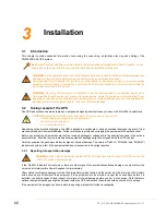
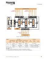
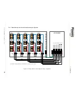
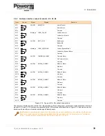
UPS CABINET
INPUT
BYPASS
OUTPUT
Cable C
Cable A
F1
F2
UPS Module 1
Rectifier
Inverter
Maint
Bypass
IA1
Static Switch
UPS INPUT
MAINS DEVICE
UPS SYSTEM INPUT
SUPPLY
UPS OUTPUT
DEVICE
UPS SYSTEM
OUTPUT
EXTERNAL MBP PANEL
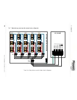
UPS CABINET
INPUT
BYPASS
OUTPUT
Cable C
Cable A
F1
F2
UPS Module 1
Rectifier
Inverter
Maint
Bypass
IA1
Static Switch
UPS INPUT
MAINS DEVICE
UPS SYSTEM INPUT
SUPPLY
UPS OUTPUT
DEVICE
UPS SYSTEM
OUTPUT
EXTERNAL MBP PANEL
Figure 3.5 External Maintenance Bypass
Содержание PowerWave 9000DPA S2
Страница 1: ...PowerWAVE 9000DPA S2 30 250 kVA User Manual ...
Страница 2: ...TS_619_00 PW9000DPA S2 User Manual 13 3 17 ...
Страница 8: ... IV TS_619_00 PW9000DPA S2 User Manual 13 3 17 ...