

3: Installation
40
TS_619_00 PW9000DPA S2 User Manual 13/3/17
3.7
Parallel-cabinet control and configuration
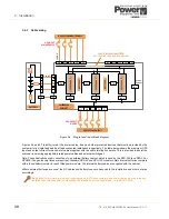
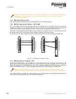
3.7.1 Parallel control bus
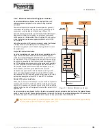
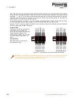
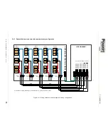
When several UPS cabinets are connected as a parallel system the modules’ electronic control system communicate with
each other by means of a parallel control bus which is connected between each cabinet and facilitates various system
control functions such as load sharing, frequency synchronisation, and synchronised load transfer. The parallel control
bus comprises a 25-way cable which is connected to an adapter board which is fitted to the parallel interface board.
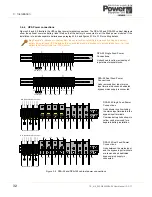
The parallel adapter boards and cables are shipped as a ‘paralleling kit’ and must be installed by the Uninterruptible
Power Supplies Ltd. commissioning engineer
Once the parallel bus cables are fitted, each cabinet is configured by means of a DIP switch to define its position in the
parallel system – one UPS cabinet is configured to act as a ‘master’ with the remaining cabinets acting as ‘slaves.’ If the
‘master’ goes faulty the next cabinet (former ‘slave’) will immediately take over the roll of the ‘master’ unit and the former
‘master’ will switch off.
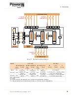
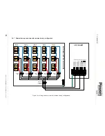
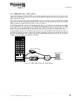
3.7.2 Multidrop
The optional ‘Multidrop’ feature, which is available only in a parallel cabinet system, requires a purpose designed
‘Multidrop’ cable to be connected between each module’s customer interface board JD12. This will be connected by the
commissioning engineer.
Note that when the multidrop feature is used, the I/O facilities of customer interface board in the ‘slave’ cabinets are all
disabled, but the customer interface board fitted to the ‘master’ cabinet remains fully functional.
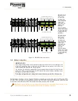
Key Point:
The parallel interface board is only fitted to the cabinet if it is used as part of parallel cabinet system.
CAUTION: All parallel control cables must be installed by the commissioning engineer.
CAUTION: Once the DIP switches have been set, DO NOT TOUCH.
Содержание PowerWave 9000DPA S2
Страница 1: ...PowerWAVE 9000DPA S2 30 250 kVA User Manual ...
Страница 2: ...TS_619_00 PW9000DPA S2 User Manual 13 3 17 ...
Страница 8: ... IV TS_619_00 PW9000DPA S2 User Manual 13 3 17 ...