
3: Installation
30
TS_619_00 PW9000DPA S2 User Manual 13/3/17
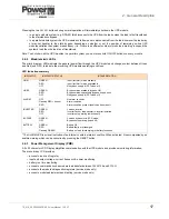
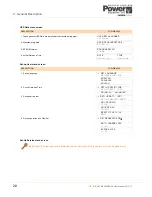
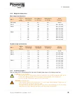
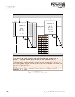
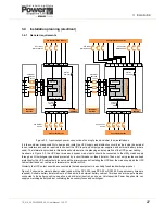
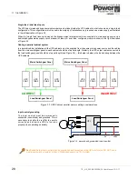
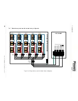
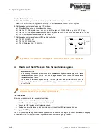
3.4.3 Cable sizing
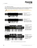
Figure 3.6 ‘Single feed’ input block diagram
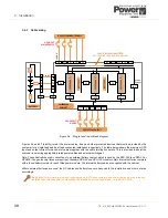
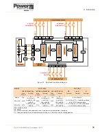
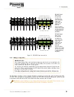
Figures 3.6 and 3.7 identify (in red) the power cables, fuses and other protective devices that must be provided by the
customer for a single-feed and dual-feed connected installation respectively. The table below shows the maximum UPS
input and output current for each set of cables together with the cable termination details. This is provided to assist the
customer in selecting appropriately rated power cables and external switchgear.
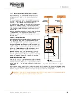
Note: These illustrations show connections to an external battery cabinet, which is used by the DPA-250 (and DPA 50 or
DPA250 if long autonomy times are required). Standard DPA-50 and DPA-150 models contain internal batteries complete
with a fused battery isolator for each fitted power module. The internal battery cables are supplied with the cabinet.
Where external batteries are used, the DC cables and battery fuses are bespoke to the installation and must be rated
accordingly.
Key Point:
This information is given for guidance only. All fuses, isolators and power cables must be rated and
installed in accordance with the prescribed IEC standards or local regulations – e.g. BS7671:2008.
Cable D
Fu
se
D
IA2‐1
Ca
b
le
C
Ca
bl
e
A
IA 1
Maint.
Bypass
3L3
3N
PE
3L1
3L2
3L3
3N
PE
3L1
3L2
PW9000DPA
CABINET
BATTERY 1
N
N
N
N
N
N
N
N
UP
S
M
o
du
le
1
BA
TTER
Y
2
1L3
1N
PE
1L1
1L2
1L3
1N
PE
1L1
1L2
2L3
2N
PE
2L1
2L2
2L3
2N
PE
2L1
2L2
INPUT/ BYPASS LINKS FITTED
1L1 – 2L1, 1L2 – 2L2, 1L3 – 2L3, 1N – 2N
PE
PE
F4
IA2‐2
UP
S
M
o
du
le
2
F5
BA
TTER
Y
3
IA2‐3
UP
S
M
o
du
le
3
F6
UPS INPUT
MAINS DEVICE
UPS SYSTEM INPUT SUPPLY
UPS SYSTEM OUTPUT
UPS OUTPUT
DEVICE
Содержание PowerWave 9000DPA S2
Страница 1: ...PowerWAVE 9000DPA S2 30 250 kVA User Manual ...
Страница 2: ...TS_619_00 PW9000DPA S2 User Manual 13 3 17 ...
Страница 8: ... IV TS_619_00 PW9000DPA S2 User Manual 13 3 17 ...