

TS_619_00 PW9000DPA S2 User Manual 13/3/17
13
2: General Description
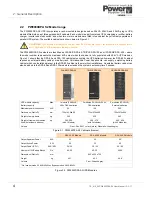
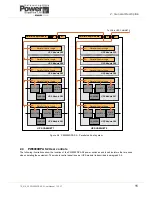
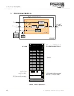
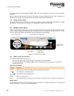
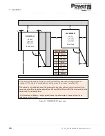
2.4.2 DPA-150 Component identification
Up to three UPS modules can be fitted, with the lower-most module identified as module 1.
The battery fuses are identified F4 to F6. F4 is associated with module 1, F5 with module 2 and F6 with module 3.
The parallel isolator switches (IA2) are labelled to identify their associated UPS module – e.g. IA2-2 pertains to module 2.
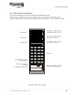
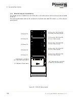
Figure 2.10 DPA-150 Cabinet details
Battery trays
UPS Customer Interface connections
(described in the Options chapter).
Parallel Isolator (1 per module)
[IA1] Maintenance Bypass Isolator
UPS Module P03
UPS Module P02
UPS Module P01
[IA2-1] [IA2-2] [IA2-3]
Battery fuse (1 per module)
[F4] [F5] [F6]
JD1 Smart Port – RS232 (Sub-D9P)
JD7 Module control panel connector
JD1 Smart Port – RS232 (Sub-D9P)
JD7 Control Panel connector
JD1 Smart Port – RS232 (Sub-D9P)
JD7 Control Panel connector
Содержание PowerWave 9000DPA S2
Страница 1: ...PowerWAVE 9000DPA S2 30 250 kVA User Manual ...
Страница 2: ...TS_619_00 PW9000DPA S2 User Manual 13 3 17 ...
Страница 8: ... IV TS_619_00 PW9000DPA S2 User Manual 13 3 17 ...