

4: Operating Procedures
44
TS_619_00 PW9000DPA S2 User Manual 13/3/17
Transfer the load to inverter:
15. If the
BYPASS
LED is green (on ALL modules), open the maintenance bypass switch.
Note: If the
BYPASS
LED is not green, repeat step 7. Seek trained advice if it still fails to light green.
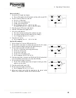
16. On the module control panel of any one UPS module:
a) Press the
UP
key once to access the menu system.
b) Use the
UP/DOWN
keys to move the cursor so that it is adjacent to
COMMANDS
then press the
ENTER
key.
c) Use the
UP/DOWN
keys move the cursor so that it is adjacent to
LOAD
TO
INVERTER
then press the
ENTER
key
d) The UPS module will transfer the load to the inverter.
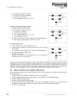
17. On the module control panel of every UPS module, verify that:
a) The
BYPASS
LED is off.
b) The
INVERTER
LED is on.
c) The LCD displays
LOAD PROTECTED
.
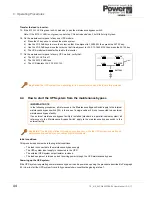
4.4
How to start the UPS system from the maintenance bypass
Initial conditions:
This procedure assumes the following initial conditions.
• The load is connected to the maintenance bypass supply.
• The UPS system input supply is connected to the UPS.
• The external UPS system output isolator is closed.
• The load equipment is turned on and receiving power through the UPS maintenance bypass.
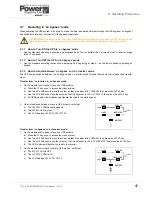
Powering up the UPS system:
If the UPS system is operating on maintenance bypass it can be powered up using the procedure described in Paragraph
4.3 (
How to start the UPS system from a fully powered-down condition
) beginning at step 7.
Key Point:
The UPS system is now operating in its ‘on-inverter’ mode and the load is fully protected.
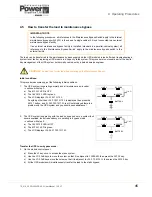
IMPORTANT NOTE
In the following procedures, all references to the ‘Maintenance Bypass Switch’ apply to the internal
maintenance bypass switch (IA1) in the case of a single cabinet if it is not connected to an external
maintenance bypass facility.
If an external maintenance bypass facility is installed (standard in a parallel-cabinet system) all
references to the ‘Maintenance Bypass Switch’ apply to the maintenance bypass switch in the
external facility.
Key Point:
If the load is not already turned on, turn it on now, while the UPS system is operating on
maintenance bypass, before you continue with this procedure.
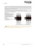
LINE 1
LINE 2
BY PASS
INVERTER
BATTERY
LOAD
Содержание PowerWave 9000DPA S2
Страница 1: ...PowerWAVE 9000DPA S2 30 250 kVA User Manual ...
Страница 2: ...TS_619_00 PW9000DPA S2 User Manual 13 3 17 ...
Страница 8: ... IV TS_619_00 PW9000DPA S2 User Manual 13 3 17 ...