
TS_619_00 PW9000DPA S2 User Manual 13/3/17
17
2: General Description
Pressing the two
ON/OFF
buttons during normal operation will immediately shut down the UPS module.
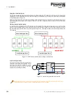
• In a single module system (e.g. DPA-50) this disconnects the UPS from the load unless the load is first transferred
to the maintenance bypass.
• In a parallel module system the UPS module shuts down and is disconnected from the load: however the load may
or may-not transfer to the static bypass, depending on whether or not the number of remaining on-line UPS
modules satisfies the system’s redundancy – i.e. if there is a sufficient number of modules remaining to support the
system’s load then the load is not transferred.
Note: To shut down all the UPS modules in a parallel system you must press both ON/OFF buttons on every module.
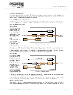
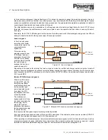
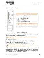
2.6.2 Module mimic LEDs
The mimic diagram LEDs indicate the general power flow through the UPS module and changes colour between Green
and Red (and OFF) to indicate the prevailing UPS module operating conditions.
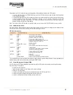
LED Indication summary
* The ALARM LED is a visual indication of an internal or external alarm condition. When activated, it is accompanied by an
audible warning which can be cancelled by pressing the RESET button.
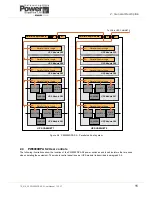
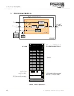
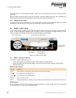
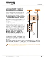
2.6.3 Power Management Display (PMD)
A 2 x 20 character LCD Display simplifies communication with the UPS module and provides monitoring information.
The menu driven LCD provides:
• access to an ‘event’ register
• input and output voltage, current, frequency & power monitoring
• battery run time monitoring
• access to commands such as module load transfer between
INVERTER
and
BYPASS
• access to the module’s diagnostics registers (service mode only)
• access to module adjustments and testing (service mode only)
INDICATOR
INDICATOR STATUS
INTERPRETATION
LINE 1
GREEN
RED
OFF
Input (rectifier) mains available
Input (rectifier) mains unavailable
No bypass supply (UPS Turned off)
LINE 2
GREEN
RED
OFF
Bypass mains available (bypass OK)
Bypass mains unavailable (bypass supply error)
No bypass supply (UPS Turned off)
ALARM*
OFF
Flashing RED + buzzer
RED
No alarm condition
Alarm condition
Alarm condition present (audio has been reset)
INVERTER
GREEN
RED
OFF
Load on inverter
Inverter fault or load transfer to inverter inhibited
Inverter not operating (switched off)
BY-PASS
GREEN
OFF
Load on bypass (or in ECO mode)
Bypass not operating (turned off)
BATTERY
GREEN
RED
Flashing GREEN
Battery OK
Battery faulty or discharged
Battery on load (discharging) or battery fuse open
Содержание PowerWave 9000DPA S2
Страница 1: ...PowerWAVE 9000DPA S2 30 250 kVA User Manual ...
Страница 2: ...TS_619_00 PW9000DPA S2 User Manual 13 3 17 ...
Страница 8: ... IV TS_619_00 PW9000DPA S2 User Manual 13 3 17 ...