KNIGHT D-SERIES SERVO HOIST OPERATION MANUAL
SECTION 5
SOFTWARE
87
Step 41.
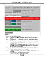
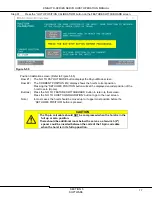
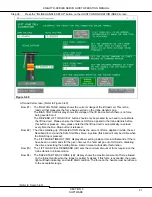
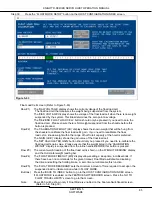
Press the “GO TO FLOAT SPEED LIMITS” button on the FLOAT TRAVEL LIMITS screen.
Figure 5-65
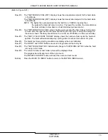
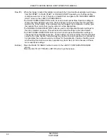
Float Speed Limits screen: (Refer to Figure 5-65)
Row #1) The ‘FLOAT MODE SPEED LIMIT (IPS)’ display shows the highest speed allowed to be
commanded while in FLOAT MODE.
The ‘FLOAT ACCEL(IPS^2)’ display shows the acceleration setpoint for analog
commanded velocity while in FLOAT MODE.
The ‘FLOAT DECEL (IPS^2)’ display shows the deceleration setpoint for analog
commanded velocity while in FLOAT MODE. This value should be set equal to or higher
than the acceleration setpoint for analog commanded velocity.
Buttons) Press the ‘GO TO FLOAT TRAVEL LIMITS’ button will go to that screen.
Press the ‘BACK TO INDEX’ button to go to the HOIST CONFIGURATION INDEX screen.
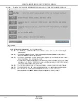
Step 42.
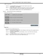
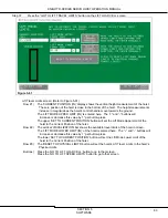
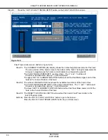
Press the “FIXTURE WEIGHT” button on the HOIST CONFIGURATION INDEX screen.
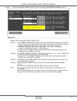
Figure 5-66
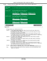
Fixture Weight screen: (Refer to Figure 5-66)
Row #1) The ‘TOTAL WEIGHT (LBS)’ display shows the full weight being suspended from
the shackle under the inline handle of the hoist. This total weight includes the weight of the
part plus the weight of the fixture (if there is a fixture).
The ‘PART WEIGHT (LBS)’ display shows the weight suspended from the shackle
of the hoist minus the weight of fixture. (Part Wt. = Total Wt. – Fixture Wt.)
Row #2) The ‘FIXTURE WEIGHT’ display shows the weight of the fixture.
You can enter a known fixture weight directly, or use the ‘SET FIXTURE WEIGHT’ button
to capture the weight. This button should not be pressed unless only the weight of the
fixture is being suspended from the Inline Handle’s shackle.
Button)
Press the ‘BACK TO INDEX’ button to go to the HOIST CONFIGURATION INDEX screen.

