background image

KNIGHT D-SERIES SERVO HOIST OPERATION MANUAL 

 SECTION 5 

SOFTWARE 

73 

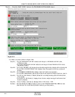
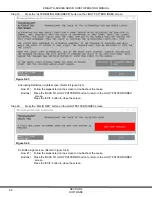
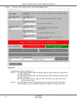
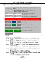
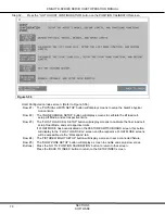
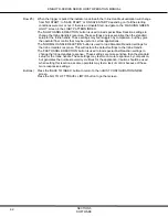
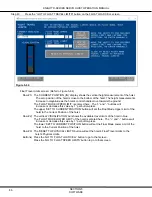
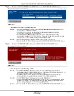
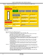
(Refer to Figure 5-51) 
 

Row #3)  The ‘TEST MODE ACCEL (IPS

2

)’ display shows the acceleration setpoint for the hoist while 

  in Test Mode. 
The ‘TEST MODE DECEL (IPS

2

)’ display shows the deceleration setpoint for the hoist while 

  in Test Mode. 
NOTE:  The higher the number placed into the ‘ACCEL’ or ‘DECEL’ input text box,  
   

   the quicker the hoist will come to a stop.  The lower the number, the more distance  


   the hoist will take to slow down so it will start slowing down sooner. 

Row #4)  The ‘TEST MODE DELAY (MS)’ value should equal or exceed the time it takes for the servo  

  to move from the upper limit to the lower limit during the test cycle. If using the settings on 
  the screen shown, the delay should be set to a minimum of 5000ms or a five second delay.        

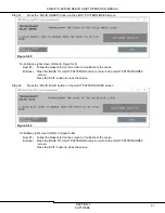
Row #5)  The ‘TEST CYCLE COUNT TARGET’ display shows the number of test cycles the hoist will  

  perform. The hoist will automatically stop cycling when it reaches this number of cycles.  

        Row #6)  The hoist’s test mode starting conditions are displayed here as indicators. 
        Row #7)  The ‘START’ and ‘STOP’ buttons are used to begin and end the test cycle. 
        Row #8)  The ‘TEST MODE INACTIVE’ indicator will change to ‘TEST MODE ACTIVE’ when the hoist  

  is moving in test mode. 

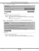
Row #9)  The current number of test mode cycles will be displayed here. 

The progress bar will keep track of the cycle count. 
The “RESET COUNTER” button will reset the number of test counts. 

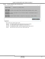
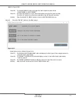
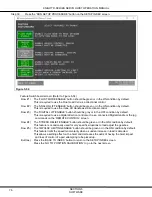
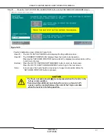
        Button) 

Press the ‘BACK TO INDEX’ button to return to the MOTION INDEX screen. 


Содержание D Series

Страница 1: ...d Operation Manual THIS MANUAL CONTAINS IMPORTANT INFORMATION REGARDING INSTALLATION SAFETY MAINTENANCE AND OPERATION OF THE KNIGHT GLOBAL SERVO HOIST AND SHOULD BE AVAILABLE TO ALL PERSONNEL RESPONSIBLE FOR USING THE HOIST REV 005_202112 ...

Страница 2: ...mon sense and judgment when performing the tasks described in this manual If any procedure seems inaccurate incomplete or unsafe please put the equipment in a safe condition and contact Knight Global service department for assistance Knight Service department s phone number is 248 375 7962 Throughout this manual there are steps and procedures that if not performed correctly can result in personal ...

Страница 3: ...ep 8 Software Adjustments If necessary 12 3 OPERATION 13 A Principle of Operation 13 B Model Number 13 C Servo Hoist Control Configuration 14 D Servo Hoist Functionality Modes 15 Run Stop 15 Shut Down 15 Start Up 15 No Mode 15 Lift Mode 15 Float Mode 16 Fault Mode 16 4 MAINTENANCE 17 A CHAIN INSPECTION 17 4 1 Inspection Overview 17 4 2 Use of Chain Safely in Any Application 18 4 3 Determining the ...

Страница 4: ...meter Array 104 F dSTS Parameter Array 104 G tPRM Parameter Array 105 H fPRM Parameter Array 105 I fSTS Status Array 112 7 TROUBLESHOOTING 115 A Troubleshooting Screens 115 7 1 Unable to Connect 115 7 2 Can t Enter Lift Mode screen 116 7 3 Can t Enter Float Mode screen 117 7 4 Can t Move Up screen 117 7 5 Can t Move Down screen 119 7 6 Slow Flashing Red Light screen 120 7 7 Fast Flashing Red Light...

Страница 5: ...the system designer system manufacturer crane or rail manufacturer installer and user to ensure that the installation and associated wiring of the Servo Hoist and components are in compliance with ANSI NFPA 70 and all applicable Federal State and Local Codes Hazardous voltages are present in the Servo Hoist and components Only properly trained and competent personnel should perform inspections or ...

Страница 6: ...he chain is centered over the hook Do not side pull or yard the chain Do not force the hook into place by hammering Ensure the load is properly seated in the saddle of the hook Never run the chain over a sharp edge Pay attention to the load at all times when operating the Servo Hoist Ensure no personnel are in the path of the load Do not lift the load over personnel Never use a Servo Hoist for lif...

Страница 7: ...tted when overloaded to allow the user to safely set the weight back down on a stable surface Run Stop Push Button If an operator needs to stop motion immediately the operator pushes the Run Stop button The system will not function until it is reset To reset the system from the Run Stop condition the operator turns the button clockwise to release it from the depressed position All virtual limits a...

Страница 8: ...use injury or death Before installing this hoist read the Safety section of this manual Follow all procedures in this section for installation and set up of the Servo Hoist Retain all product information supplied with the Servo Hoist for future reference Ensure that the supporting structure is able to support the weight of the system and load The structure should be able to support 300 percent of ...

Страница 9: ... guide assembly and AC Plug Coiled Cable Assembly In most cases a 19 pin coil cable carries signals from the control handle to the Servo Hoist Some examples are Analog load cell voltages digital inputs and outputs including direction commands Lift Mode Float Mode and Run Stop signals In some cases a 19 pin straight cable carries some or all of these signals to the Servo Hoist Control Handle The ma...

Страница 10: ...r signs of damage or missing parts 1 Slide the trolley or adapter plate into the trolley mounting plate on top of the Servo Hoist Refer to Figure 2 2 CAUTION Ensure that there is a 2 two point connection when using the universal adapter plate to hang the hoist from a structure Refer to Figure 2 3 2 Insert the 2 two 13x1 grade 8 or better socket head cap screws SHCS and 2 two washers NOTE The troll...

Страница 11: ...rnating sides Repeat this procedure on the other clamp Each nut should be tightened to a minimum of 15 ft lbs 5 Follow the steps below for trolley or adapter plate 6 Insert cable through the center hole on the trolley bracket which is attached to the hoist and place 2 two Crosby clamps on the other end of the cable Refer to Figure 2 6 7 Secure the 2 two Crosby clamps snug to the thimble repeating ...

Страница 12: ...n nest Secure both of the chain s retaining bolts through the provided holes in the chain nest Refer to Step 2d 4mm and 5mm Chain Installation 6 Loosen the 2 two M4 screws holding the 19 pin receptacle and slide it out of the control handle s housing Refer to Figure 2 10 7 Connect the 19 pin connector to the receptacle slide it back into the control handle s housing and secure the 2 two M4 screws ...

Страница 13: ... with no twists from the gear box down to the chain nest 4 Install the last link of the Safety Drop Stop SDS chain into the lower portion of the chain nest in front of the load chain Ensure that the SDS chain is kept parallel to the load chain 5 Install the bolt provided into the bottom bolt hole in the chain nest and through the last link in the SDS chain Refer to Figure 2 13 6 Ensure that the la...

Страница 14: ...y a twist lock plug Refer to Figure 2 16 Standard or fed by a hard wired circuit provided by end user Refer to Figure 2 17 CE Compliant 2 The red light on the Run Stop button will illuminate when power is provided to the Servo Hoist system Step 4 Releasing the Run Stop button The Run Stop button is engaged for shipping purposes 1 Turn Run Stop button a quarter of a turn clockwise to release the Ru...

Страница 15: ...ortable height Figure 2 19 NOTE A continuously flashing GREEN light indicates a safe start activation fault The system is sensing commanded motion during the Power Up sequence Remedy Analog Handle Release the handle and verify that the GREEN light illuminates solid If the GREEN light still flashes after the handle is released refer to section 7 Troubleshooting Step 6 Test Hoist Movement Test the S...

Страница 16: ...or a specific application Refer to the following first time adjustments in section 5 Software Verify that the Float load cell is zeroed correctly see Section 5 E Step 36 Verify the hoist s maximum allowed weight This is also known as the Up Stop weight of the hoist See Section 5 E Step 36 Verify the hoist s minimum weight This is also known as the Down Stop or pay out weight of the hoist See Secti...

Страница 17: ...ated capacity D designates that this is a D Series hoist S designates our Safety Drop Stop feature The next 3 three numbers indicate the voltage The following number indicates the phase of the system The last 3 three digits are a Knight control servo code The hoist s model number and serial number can be found on the Knight identification label located on the Servo Hoist Figure 3 1 Servo Hoist Mod...

Страница 18: ...KNIGHT D SERIES SERVO HOIST OPERATION MANUAL SECTION 3 OPERATION 14 C Servo Hoist Control Configuration Figure 3 2 D Series Servo Hoist ...

Страница 19: ...Servo Hoist powers up the unit will be in this energy saving mode No mode can also be triggered if the hoist is inactive for set time period By default this time out feature is turned off When in No Mode the holding brake will engage and power will be removed from the motor When the unit is in No Mode the OCI s GREEN BLUE and RED indicators will be off Lift Mode Press the GREEN Lift button to plac...

Страница 20: ... change to Lift Mode and then it will move up or down Press the GREEN Lift push button and the unit will change into Lift Mode Allow the Float Mode Timeout timer to expire This timer is set at the factory to 0ms of non use a value of 0 turns the timeout feature OFF To change this timer refer to section 6G tPRM Parameter Array in the parameter descriptions section NOTE The part must be picked up wh...

Страница 21: ...d Person A person who by possession of a recognized degree in an applicable field or certificate of professional standing or who by extensive knowledge training and experience has successfully demonstrated the ability to solve or resolve problems relating to the subject matter at hand Designated Person A person selected or assigned by the employer or the employer s representative as being competen...

Страница 22: ...g load limit on the identification tag Knots Twists and Kinks Ensure chain is not twisted knotted or kinked before lifting load Chains should not be shortened with knots bolts or other make shift devices Sharp Edges Protect chain with padding when lifting sharp edged loads Abrupt Movement Lift and lower loads smoothly Do not jerk Extreme Temperatures Do not expose alloy chain to temperatures of 40...

Страница 23: ...ads and very rarely to maximum loads Moderate Service Hoist and chains normally subjected to moderate loads but fairly frequently to maximum loads Heavy Service Hoist and chains normally subjected to loads of heavy magnitude and frequently to maximum loads Very Heavy Service Hoist and chains regularly subjected to maximum loads 4 3 2 Service Class Duty Cycle Service Class is determined by the tota...

Страница 24: ...ry Day Additionally the operator should check the system continually during operation to ensure that no malfunctions are occurring such as abnormal noises or binding of the chain 4 4 1 1 What to Look for During a Frequent Inspection Operator should examine the chain throughout its working length to detect any evidence of wear distortion or external damage Equipment should be operated under a load ...

Страница 25: ...uld be done to permit detailed inspection 4 4 2 1 Recommendations for Periodic Inspections Perform the inspection detailed under section 4 4 1 1 What to Look for During a Frequent Inspection of this manual Next the chains should be cleaned for inspection using any cleaning method that will not cause damage Adequate lighting should be provided for the person inspecting the chain The chain should be...

Страница 26: ...s indicates that the chain s length has increased by 2 or more and should be removed from service and replaced with new chain 5 Perform this inspection in multiple sections of the chain working up to the sprocket Figure 4 3 C If Chain Gauge is Not Available Select an unworn un stretched length of the load chain Suspend the chain vertically under tension Use a caliper type gauge to measure the accu...

Страница 27: ...er any 5 7 9 11 or 13 links as appropriate exceeds that of the unused chain by 2 Figure 4 4 4 4 2 2 Recommended Record Keeping for Periodic Inspections Adequate records as a part of periodic inspection are essential for the proper use of calibrated chains The chain record should include a complete description and identification of the new chain the date and results of each inspection the date and ...

Страница 28: ...coat of SAE 50 to 90 EP oil or equivalent machine gear oil Ensure that oil is applied to the bearing surfaces of the load chain links Wipe off excess oil from the load chain surfaces Substitute a dry lubricant for use in dusty environments Knight recommends Demag Chain Grease P N 665 009 44 Refer to Figure 4 5 Chain Lubrication Lubricate hook and safety latch pivot points with same lubricant used ...

Страница 29: ...spection Documented If the problem persists replace the chain Cycle the Run Stop button and ensure it functions correctly 4 5 1 2 Load Shackle Check the shackle for signs of wear Ensure the load shackle is not cracked nicked or gouged Replace the shackle as necessary Confirm all cotter pins and or keepers are in place If any of these abnormal conditions are evident the Servo Hoist should be taken ...

Страница 30: ...at optimum efficiency Repair or replace if needed 4 5 2 6 Wiring Check for broken loose missing and worn wires Check all electrical cables for signs of age wear or damage and make sure all connections are tight and secure Repair or replace if needed 4 5 2 7 Electrical Enclosures Disconnect Boxes and Circuit Breakers Check for obvious signs of damage and repair or replace if needed Verify disconnec...

Страница 31: ...Ensure that all labels are intact and legible Replace as necessary Refer to Figure 4 6 Figure 4 6 If any of the labels or warning tags listed above are missing contact Knight Global at 248 377 4950 to order replacements CE Identification Identification Enclosure Cover Label Voltage Warning Tags ...

Страница 32: ...Home Step 2 Measure the distance from the top of the inline handle to the bottom of the servo hoist Refer to Figure 4 8 Step 3 Record this measurement because it will be used in section 4 6 1 Resetting the Encoder Offset Figure 4 8 Step 4 Move the inline handle down to a comfortable working height Step 5 Remove ALL of the load that is attached to the hoist under the inline handle This includes the...

Страница 33: ... releases the Safety Drop Stop SDS chain and the top bolt releases the Load chain A M4 Allen wrench will be required Refer to Figure 4 9 Figure 4 9 Step 9 Remove the bottom bolt and the SDS chain first and then remove the top bolt and load chain Ensure that the inline handle is supported before the load chain is disengaged from the chain nest Step 10 Remove the side covers from Servo Hoist Refer t...

Страница 34: ... Refer to Figure 4 12 Figure 4 12 Step 16 Power the system back up Step 17 To enable the chain pay out sequence using the Operator Control Interface OCI twist the Run Stop button clockwise to enable the hoist Within 3 seconds press the Run Stop button press and release the Green Lift button and then the Blue Float button twist the Run Stop button clockwise and release This will start the pay out m...

Страница 35: ...the correct length so it has slack in it when the load chain is properly connected Step 25 Ensure that both chains are parallel with no twists from the gear box down to their respective ends Step 26 Count down seven links from the end of the load chain Cut the seventh link so the SDS chain is six links longer than the load chain Refer to Figure 4 13 Figure 4 13 Step 27 Install the safety chain ide...

Страница 36: ...t is installed in front of the last link of the load chain and into the chain nest Refer to Figure 4 16 Figure 4 16 Step 32 Next the last link of the SDS chain is installed into the bottom slot of the chain nest The chain must be kept parallel with no twists The bolt is installed through the last link of the SDS and into the chain nest Refer to Figure 4 17 Figure 4 17 Step 33 Reinstall the large O...

Страница 37: ...Encoder Offset Please refer to the Position Calibration screen found in section 5 E Step 31 WARNING Do NOT raise the servo handle above the recorded measurement obtained in Step 3 of section 4 6 Load and Safety Drop Stop Chain Replacement Normal Maintenance or damage may be done to the servo ...

Страница 38: ... Figure 4 19 Step 2 To enable the chain pay out sequence using the Operator Control Interface OCI twist the Run Stop button clockwise to enable the hoist Within 3 seconds press the Run Stop button press and release the Green Lift button and then the Blue Float button twist the Run Stop button clockwise and release This will start the pay out mode after three to ten seconds If the direction is inco...

Страница 39: ... chain pocket opening Step 8 Ensure that the new load chain is aligned correctly so that it will enter the gear box properly Step 9 Ensure that there is tension on the chain replacement tool so that it is pulled into the gear box when the payout mode is started Step 10 Restart the pay out mode by following the procedure listed in Step 2 above Step 11 This will feed the new load chain and SDS chain...

Страница 40: ... functions to initially verify These functions can be accessed from various screens located under the Setup section KSS Workspace tree location User Level Basic Knight WO Hoist Configuration 1 The float load cell is reading correctly This can be verified in the following section 5 E Review the Hoist Knight Servo Studio Software under Step 36 KSS Workspace tree location User Level Basic Knight WO H...

Страница 41: ...eeded to connect to a Knight Servo Hoist Refer to Figure 5 1 Laptop running Microsoft Windows 7 or above Customer Supplied Ethernet Cable with 1 RJ45 connector and 1 M12 4 pin connector The Knight Servo Studio software package Note The Knight Servo Studio software and an Ethernet Cable can be ordered from Knight P N KCA1052 Figure 5 1 ...

Страница 42: ...o Studio Software Package Setup Step 1 Setup the Ethernet communication settings for your laptop a Using a Microsoft Windows based PC open the Network and Sharing Center b Right click on Local Area Connections Select Properties Refer to Figure 5 2 Figure 5 2 c Select Internet Protocol Version 4 TCP IPv4 Select Properties d Select Use the following IP address In most cases the laptop s IP Address s...

Страница 43: ... Figure 5 4 Step 3 Double click on the blue Knight Servo Studio software icon located on the desktop and allow the Knight Servo Studio software to load Step 4 When the software loads choose the Open Project from Device option The standard IP Address is automatically loaded into the Network Configuration box The IP Address for the hoist will be located on a label next to the M12 ENET receptacle loc...

Страница 44: ... and select the Connect button If the communications are operating correctly the red Disconnected box will turn to a green Connected box Refer to Figure 5 6 If the Knight Servo Studio software does not connect to the hoist recheck all of the connections and ensure that the hoist has its 240VAC power connected Figure 5 6 ...

Страница 45: ...t Refer to Figure 5 7 Figure 5 7 Step 2 Select a folder where to save the backup copy of the file Ensure the Knight Work Order and System number is included in the filename Refer to Figure 5 8 Knight suggests that a Controls folder be created as well as subdirectories for each servo The hoist s Work Order number should be used as the name for these new subdirectories i e Controls 123456 Figure 5 8...

Страница 46: ...igure 5 9 a While connected to the hoist open a web browser Google Chrome is preferred b Browse to the address for the Yaskawa PLC 192 168 2 101 c The User pulldown allows the Log In screen to be selected Figure 5 9 Step 6 Log into the Yaskawa controller Refer to Figure 5 10 To Log In to the Yaskawa drive the following values need to be entered in at the Log In Dialog Box Note These are the defaul...

Страница 47: ...Welcome Screen with the Yaskawa default settings when logged in as Admin Refer to Figure 5 11 Figure 5 11 Step 8 To create a new archive file return to the web browser Refer to Figure 5 12 a Go to the Setup pulldown menu and select Archive b On the Archive page select Receive Figure 5 12 ...

Страница 48: ...n ONLY click the button ONCE Refer to Figure 5 13 Figure 5 13 Step 10 Click the Save button to back up the ZIP file to your MyDocs folder or the Save As button to direct the ZIP file to another folder Refer to Figure 5 14 If the Save prompt does not appear Windows normally saves the archive file to your PC s Downloads folder Figure 5 14 ...

Страница 49: ...banner will be displayed indicating the current status Downloading archive Allow this to complete Refer to Figure 5 15 Figure 5 15 Step 12 Send a copy of the newly saved Archive zip file to Knight s Servo Team at servos knightglobal com Step 13 You have completed the Yaskawa Servo Backup procedure ...

Страница 50: ... Step 2 Press the Run Stop button Step 3 Remove the input power from the system Step 4 If possible it is recommended to bring the hoist to ground level to replace the components listed in this section All components listed will need to be replaced with an exact match to ensure functional requirements in order to run correctly Motors can be replaced per Knight procedures This will cause a loss of p...

Страница 51: ...own until it snaps into place iv Power up the system b If you replaced the PLC Drive or need to update the Archive on the PLC please log into the Yaskawa Admin Panel as shown in section 5 C steps 5 6 and 7 Continue to follow the appropriate steps listed in that section c If you are updating the PLC Archive with a new one supplied by Knight the correct Archive files should already be loaded If you ...

Страница 52: ...chive Link iv Select the location of where the ZIP file is located on your laptop by using the Open dialog box v Select the Send option located on the right hand side of the Send Archive to Controller dialog box Refer to Figure 5 18 Figure 5 18 vi When the send progression bar to the left of the Send option is complete then press the Install pushbutton in the lower right hand corner of this Dialog...

Страница 53: ... the Reboot button Refer to Figure 5 20 Figure 5 20 viii On the Reboot pop up screen press the Reboot button This will make all of the recent changes persistent in the Yaskawa controller Refer to Figure 5 21 Figure 5 21 ix After the reboot is finished you will have to log back into the Yaskawa drive ...

Страница 54: ... Drive Parameters will initially show a Not Verified result Click on the Verify to check the loaded User Parameters parameters The result will show as Verified or MISMATCH Pn Any mismatch result means the User Parameters must be written from the PLC to the Drive NOTE Pn825 will occasionally show up as a mismatch drive parameter this should be disregarded iii Make sure to use the Write command unde...

Страница 55: ...e Write Button Refer to Figure 5 24 Figure 5 24 v Confirm that the User Parameters write function is Verified Refer to Figure 5 25 Figure 5 25 vi Unplug the power to the servo wait 30 seconds and plug back in power vii Your PLC Drive I O and motor should all be functional and ready to be setup for your application ...

Страница 56: ... 5 26 Upper The interface allows the user to Connect Disconnect to and from the hoist The connection Alarm and Warning states are also shown Lower There are 5 five buttons that will display different overview screens for the Servo Hoist Safety Requirements to use the hoist correctly Status Screens that show the condition of the hoist Troubleshooting Screens that help diagnose common problems the h...

Страница 57: ...e 5 27 Step 4 Press the STATUS button on the Start screen Figure 5 28 Status Index screen Refer to Figure 5 28 Row 1 The SYSTEM STATUS button will display a screen showing the status of the hoist and its modes Row 2 The I O STATUS button will display a screen showing the inputs and outputs of the hoist Row 3 The ALARMS WARNINGS button will display a screen showing any active Drive Alarms or Warnin...

Страница 58: ...ws the status of the hoist If the indicator box is Green the object is ON if the box is Gray the object is OFF and if the box is Red then the object is disabled or faulted Lower The lower section of this screen shows the status of the software modes of the hoist If the indicator box is Green the object is active if the box is Gray the object is inactive Button Press the BACK TO INDEX button to ret...

Страница 59: ...een Figure 5 30 I O Status screen Refer to Figure 5 30 Upper The indicator boxes to the left of the digital input or output descriptions will change color if they activate If the box is Green the I O point is ON if the box is Gray the I O point is OFF Button Press the BACK TO INDEX button to return to the STATUS INDEX screen ...

Страница 60: ...Figure 5 31 Upper The upper section of this screen shows any Drive Alarms that are active The current Alarm can be reset by pressing the FAULT RESET button Lower The lower section of this screen shows any Drive Warnings that are active The Up Stop and Down Stop warnings will illuminate yellow when active Button Press the BACK TO INDEX button to return to the STATUS INDEX screen ...

Страница 61: ...button will display screens showing the steps to troubleshoot why the hoist cannot enter Lift or Float Mode Row 3 The CAN T MOVE button will display screens showing the steps to troubleshoot why the hoist cannot move up or down Row 4 The DIAGNOSE LIGHT PATTERN button will display a screen showing the indicator light patterns for the red green and blue lights Row 5 The DIAGNOSE MOTION DRIFT button ...

Страница 62: ...rn to the TROUBLESHOOTING INDEX screen Step 10 Press the CAN T ENTER A MODE button on the TROUBLESHOOTING INDEX screen Figure 5 34 Can t Enter Lift Mode screen Refer to Figure 5 34 Row 1 Follow the steps listed on this screen to troubleshoot if the software is allowing the hoist to enter Lift Mode Row 2 Follow the steps to see if the hoist is registering the operator s inputs Buttons Press the BAC...

Страница 63: ...ODE screen Figure 5 35 Can t Enter Float Mode screen Refer to Figure 5 35 Row 1 Follow the steps listed on this screen to troubleshoot if the software is allowing the hoist to enter Float Mode Buttons Press the GO TO CAN T ENTER LIFT MODE button to return to that screen Press the BACK TO INDEX button to return to the TROUBLESHOOTING INDEX screen ...

Страница 64: ...andle The ACTIVE UP STOP WEIGHT LB display shows the weight at which an up stop will activate Row 3 The CURRENT POSITION IN display shows the hoist s current position The ACTIVE UPPER LIMIT IN display shows the set upper limit that the hoist can move to Row 4 The LIFT LC VOLTAGE V Display shows the live voltage reading of the lift load cell tied to the handle The FLOAT LC VOLTAGE V display shows t...

Страница 65: ...ht The ACTIVE DOWN STOP WEIGHT LB display shows the weight at which a down stop will activate Row 3 The CURRENT POSITION IN display shows the hoist s current position The ACTIVE LOWER LIMIT IN display shows the set lower limit that the hoist can move to Row 4 The LIFT LC VOLTAGE V Display shows the live voltage reading of the lift load cell tied to the handle The FLOAT LC VOLTAGE V display shows t...

Страница 66: ...ight troubleshooting screen Press the ALTERNATING RED GREEN button to bring up the Alternating Red Green Lights troubleshooting screen Row 2 Press the SOLID RED button to bring up the Solid Red Light troubleshooting screen Press the SOLID GREEN button to bring up the Solid Green Light troubleshooting screen Press the SOLID BLUE button to bring up the Solid Blue Light troubleshooting screen Press t...

Страница 67: ...he FAST FLASHING RED button to bring up the Fast Flashing Red Light troubleshooting screen Button Press the BACK TO LIGHT PSTTERNS button to return to the LIGHT PATTERN INDEX screen Step 16 Press the SLOW FLASHING RED button on the FLASHING RED INDEX screen Figure 5 40 Slow Flashing Red Light screen Refer to Figure 5 40 Row 1 Follow the steps listed to troubleshoot the cause Buttons Press the BACK...

Страница 68: ...ton on the FLASHING RED INDEX screen Figure 5 41 Fast Flashing Red Light screen Refer to Figure 5 41 Row 1 Follow the steps listed on the screen to troubleshoot the cause Buttons Press the BACK TO FLASHING RED INDEX button to return to the FLASHING RED INDEX screen Press the EXIT button to close the screen ...

Страница 69: ...tton on the LIGHT PATTERN INDEX screen Figure 5 42 Flashing Green Light screen Refer to Figure 5 42 Row 1 Follow the steps listed on the screen to troubleshoot the cause Buttons Press the BACK TO LIGHT PATTERNS button to return to the LIGHT PATTERN INDEX screen Press the EXIT button to close the screen ...

Страница 70: ...ot the cause Buttons Press the BACK TO LIGHT PATTERNS button to return to the LIGHT PATTERN INDEX screen Press the EXIT button to close the screen Step 20 Press the SOLID RED button on the LIGHT PATTERN INDEX screen Figure 5 44 Solid Red Light screen Refer to Figure 5 44 Row 1 Follow the steps listed on the screen to troubleshoot the cause Buttons Press the BACK TO LIGHT PATTERNS button to return ...

Страница 71: ...e Buttons Press the BACK TO LIGHT PATTERNS button to return to the LIGHT PATTERN INDEX screen Press the EXIT button to close the screen Step 22 Press the SOLID BLUE button on the LIGHT PATTERN INDEX screen Figure 5 46 Solid Blue Light screen Refer to Figure 5 46 Row 1 Follow the steps listed on the screen to troubleshoot the cause Buttons Press the BACK TO LIGHT PATTERNS button to return to the LI...

Страница 72: ...n to troubleshoot the cause Buttons Press the BACK TO LIGHT PATTERNS button to return to the LIGHT PATTERN INDEX screen Press the EXIT button to close the screen Step 24 Press the DIAGNOSE MOTION DRIFT button on the TROUBLESHOOTING INDEX screen Figure 5 48 Motion Drift screen Refer to Figure 5 48 Row 1 Follow the steps listed on the screen to troubleshoot the cause Button Press the BACK TO INDEX b...

Страница 73: ...n Figure 5 49 Motion Index screen Refer to Figure 5 49 Row 1 The PAYOUT MODE button will display the chain payout screen Row 2 The TEST MODE button will display the Test Mode screen Row 3 The REMOTE CONTROL button will display the remote control screen Button Press the EXIT button to return to the hoist s Start screen ...

Страница 74: ...ed and is not intended for normal use The most common use is during chain replacement Row 1 The PAYOUT MODE SPEED IPS display shows the speed that will be commanded while Payout Mode is active Payout Mode is limited to a maximum 5 Inches per Second Row 2 The PAYOUT MODE BACKOFF DISTANCE IN display shows the position amount that will be used in the opposite direction of travel if the torque limit i...

Страница 75: ...l be limited to in Payout Mode when paying in chain or paying out chain Row 4 The ACTUAL TORQUE display shows the amount of torque that the motor is running at Row 5 The PAY IN button will issue a reverse upward direction command There is normally a 3 second delay after issuing the command before motion starts Row 6 The PAY OUT button will issue a run in forward downward direction command There is...

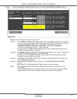
Страница 76: ...t the hoist will travel to while in Test Mode The TEST MODE LOWER LIMIT IN display shows the lower limit that the hoist will travel to while in Test Mode Note When the Start button is pressed the servo will move to the upper limit and then continue the test cycle Row 2 The TEST MODE VELOCITY IPS display shows the speed that will be commanded while Test Mode is active Test Mode is limited to a maxi...

Страница 77: ...ower limit during the test cycle If using the settings on the screen shown the delay should be set to a minimum of 5000ms or a five second delay Row 5 The TEST CYCLE COUNT TARGET display shows the number of test cycles the hoist will perform The hoist will automatically stop cycling when it reaches this number of cycles Row 6 The hoist s test mode starting conditions are displayed here as indicato...

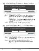
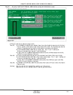
Страница 78: ...cceleration setpoint for digital commanded velocity The DIGITAL DECELERATION IPS 2 display shows the deceleration setpoint for digital commanded velocity This value should be set equal to or higher than the acceleration setpoint for digital commanded velocity Row 4 The FLOAT MODE INACTIVE indicator will change to FLOAT MODE ACTIVE when the hoist is in Float Mode The FLOAT button will cause the hoi...

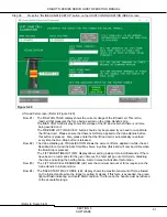
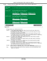
Страница 79: ... Press the BACK TO INDEX button to return to MOTION INDEX screen Step 29 Press the SETUP button on the Start screen Figure 5 53 Setup Index screen Refer to Figure 5 53 Row 1 The RUN SETUP PROCEDURE button will display the first screen of the setup procedure to setup the hoist s parameters Row 2 The RESET TO DEFAULTS button will display a screen to set all the hoist s parameters to factory default ...

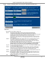
Страница 80: ...by default This is required to use a digital direction control such as a connected Digital Handle or the jog commands on the REMOTE CONTROL screen Row 4 The STRESS RELIEF ENABLE button should be green or in the ON condition by default This feature is occasionally used for very specific situations to load adjust the gearbox Row 5 The IMPULSE LIMITING ENABLE button should be green or in the ON condi...

Страница 81: ... the displayed encoder position of the hoist to zero Home Buttons Press the GO TO FEATURE SWITCHBOARD button to return to that screen Press the GO TO HOIST CONFIGURATION button to go to the next screen Note In most cases the hoist should be moved up to it upper most position before the SET HOME POSITION button is pressed CAUTION The 19 pin coil cable should NOT be compressed when the hoist is in t...

Страница 82: ...s Row 3 The FLOAT LOAD CELL SETUP button will display screens to calibrate the float load cell setup Float Mode and set respective limits If FLOAT MODE has been disabled on the FEATURE SWITCHBOARD screen this button will display to the FLOAT LOAD CELL screen and the respective FLOAT MODE screens will be accessible via the Workspace tab Row 4 The FIXTURE WEIGHT SETUP button will display a screen to...

Страница 83: ... the hoist to the Current Position of the hoist Row 2 The LOWER PHYSICAL LIMIT IN of the hoist is entered here The and buttons will increase or decrease this value by 1 per button press The lower SET TO CURRENT POSITION button will set the Lower Physical Limit of the hoist to the Current Position of the hoist Row 3 The RESET TO FACTORY LIMITS button will set the hoist s Physical Travel Limits to t...

Страница 84: ... higher than the hoist s capacity This weight can be set lower so the hoist can t lift heavier objects than the parts its designed for such as dunnage containers etc Buttons Press the GO TO PHYSICAL TRAVEL LIMITS button to go to that screen Press the GO TO PHYSICAL SPEED LIMITS button to go to that screen Step 35 Press the GO TO PHYSICAL SPEED LIMITS button on the PHYSICAL WEIGHT LIMITS screen Fig...

Страница 85: ...ed every time the Run Stop button is released Row 2 The Inline Handle grip VISUALIZATION shows the amount of force applied in white the set Deadband in red and the Safe Start Max Force in yellow this band will only be visible when the Run Stop is pressed The LIFT MODE TIMEOUT MS display allows setting a sleep time in milliseconds If there have been no commands for the given timeout the hoist will ...

Страница 86: ...tor finer control that may be useful in certain applications The NORMAL HANDLE REACTION button is used to load Standard Reaction settings for the Inline Handle s response This will restore the default settings to the Inline Handle The FAST HANDLE REACTION button is used to load special Fast Reaction settings to change the Inline Handle s response These settings are more sensitive than the standard...

Страница 87: ...his value by 1 per button press The upper SET TO CURRENT POSITION button will set the Lift Mode Upper Limit of the hoist to the Current Position of the hoist Row 2 The vertical VISUALIZATION bar shows the available travel limits of the hoist in Green The LIFT MODE LOWER LIMIT IN of the hoist is entered here The and buttons will increase or decrease this value by 1 per button press The lower SET TO...

Страница 88: ...ded velocity Row 2 The DIGITAL SLOW SPEED IPS display shows the command velocity for the slow jog function while in LIFT MODE The DIGITAL FAST SPEED IPS display shows the command velocity for the fast jog function while in LIFT MODE Row 3 The DIGITAL LIFT ACCEL IPS 2 display shows the acceleration setpoint for digital commanded velocity while in LIFT MODE The DIGITAL LIFT DECEL IPS 2 display shows...

Страница 89: ...ferred The GAIN LB V display shows the gain value of the float load cell The SET CALCULATED GAIN button should only be pressed if you need to re calibrate the float load cell s gain value Please ensure that the weight listed in the CALIBRATION WEIGHT display is suspended from the inline handle BEFORE this button is pressed Row 3 The current weight reading of the float load cell is shown on the WEI...

Страница 90: ...is value by 1 per button press The upper SET TO CURRENT POSITION button will set the Float Mode Upper Limit of the hoist to the Current Position of the hoist Row 2 The vertical VISUALIZATION bar shows the available travel limits of the hoist in blue The FLOAT MODE LOWER LIMIT of the hoist is entered here The and buttons will increase or decrease this value by 1 per button press The lower SET TO CU...

Страница 91: ...O INDEX button to go to the HOIST CONFIGURATION INDEX screen Step 42 Press the FIXTURE WEIGHT button on the HOIST CONFIGURATION INDEX screen Figure 5 66 Fixture Weight screen Refer to Figure 5 66 Row 1 The TOTAL WEIGHT LBS display shows the full weight being suspended from the shackle under the inline handle of the hoist This total weight includes the weight of the part plus the weight of the fixt...

Страница 92: ...UP will activate Slow Zone functions while moving in an upward direction based upon the hoist s loaded unloaded conditions and their corresponding position setpoints The SLOW MOVING DOWN UP will activate Slow Zone functions while moving in either direction based upon the hoist s loaded unloaded conditions and their corresponding position setpoints Row 2 The INVERT ZONE inverts the function of the ...

Страница 93: ...ctions while the hoist is loaded and moving downwards The SLOW ZONE PART LOADED SPEED IPS display shows the highest velocity that will be commanded while the hoist is loaded Row 5 The CURRENT POSITION IN display shows the current position of the hoist in inches The current speed of the hoist is shown on the CURRENT VELOCITY IPS display and the horizontal SPEEDOMETER bar Button Press the BACK TO IN...

Страница 94: ...ore resetting the absolute encoder s position Row 2 Pressing the RESET ABSOLUTE ENCODER POSITION will reset the encoder position in relation to the drive and the zero Home position will need to be established again see Step 18 This will also reset the Yaskawa Alarm Code 810 Row 3 The GO TO POSITION CALIBRATION button goes to the Position Calibration screen Button Press the BACK TO INDEX button to ...

Страница 95: ...ll be 192 168 2 101 in most cases Step 2 The web page will be similar to what is shown in Figure 5 67 The information shown listed under the Alarms History TAB includes the Error Class Axis Error Id Source Timestamp and Description Figure 5 70 Step 3 To receive a more complete description of the fault press the Alarms Reference TAB Find the row that has the matching Error Class and Axis Error Id o...

Страница 96: ...VO HOIST OPERATION MANUAL SECTION 5 SOFTWARE 92 Step 4 Any Drive Fault that is currently affecting the system can be found on the screen KSS Workspace tree location Status Alarms Warnings Refer to Figure 5 72 Figure 5 72 ...

Страница 97: ...are Boolean bits being sent to and from the hoist to the Knight Servo Studio and are displayed at KSS Workspace tree location Knight WO Parameters bPRM bPRM 0 Fault Reset Variable Units Boolean 0 Off 1 On Description Command bit sent from KSS to the drive to reset current faults KSS Workspace tree location Knight WO Status Alarms Warnings Row 3 bPRM 1 Spare bPRM 2 Exit Mode Variable Units Boolean ...

Страница 98: ...nits Boolean 0 Off 1 On Description A digital up command from KSS The JOG UP button on the Remote Control screen has been pressed KSS Workspace tree location Knight WO Motion Remote Control Row 7 bPRM 14 Digital Down Variable Units Boolean 0 Off 1 On Description A digital Down command from KSS The JOG DOWN button on the Remote Control screen has been pressed KSS Workspace tree location Knight WO M...

Страница 99: ...PHYSICAL LIMITS button in the Lift Travel Limits screen has been pressed KSS Workspace tree location Knight WO Hoist Configuration Lift Travel Limits Row 3 bPRM 25 Set Lift Upper Travel Limit Variable Units Boolean 0 Off 1 On Description The SET CURRENT POSITION button on the Lift Travel Limits screen has been pressed KSS Workspace tree location Knight WO Hoist Configuration Lift Travel Limits Row...

Страница 100: ...Setup Feature Switchboard Row 1 bPRM 37 Enable Digital Lift Mode Variable Units Boolean 0 Off 1 On Description This parameter is used to enable or disable Digital Lift Mode KSS Workspace tree location Knight WO Setup Feature Switchboard Row 3 KSS Workspace tree location Knight WO Motion Remote Control Row 1 bPRM 38 Enable Analog Lift Mode Variable Units Boolean 0 Off 1 On Description This paramete...

Страница 101: ... to set this new offset KSS Workspace tree location Knight WO Setup Position Calibration Row 4 bRPM 100 through bPRM 111 Spare B bSTS Status Array This parameter array lists the Boolean Status variables of the Servo Hoist that are made available to the Knight Servo Studio KSS The parameters listed in the bSTS array are Boolean bits being sent from the hoist to the Knight Servo Studio and are displ...

Страница 102: ...t WO Status System Status Row 3 bSTS 9 Digital I O OK Variable Units Boolean 0 Off 1 On Description This parameter displays a 1 if the servo drive is communicating with the VIPA remote I O KSS Workspace tree location Knight WO Status System Status Row 3 bSTS 10 Drive Homed Variable Units Boolean 0 Off 1 On Description This parameter displays a 1 if the servo drive home position has been establishe...

Страница 103: ... ready to go into Payout mode bSTS 20 Test Mode Active Variable Units Boolean 0 Off 1 On Description This parameter displays a 1 if the servo drive is currently in Test mode KSS Workspace tree location Knight WO Status System Status Row 9 bSTS 21 Test Mode Allowed Variable Units Boolean 0 Off 1 On Description This parameter displays a 1 if the servo drive may enter Test mode bSTS 22 Test Counts Co...

Страница 104: ... the float load cell and slow the hoist to reduce the impact on the system Instead of suddenly moving the load upwards the hoist senses the impulse and automatically slows down to a controlled speed KSS Workspace tree location Knight WO Troubleshooting Can t Move Up Step 5 KSS Workspace tree location Knight WO Troubleshooting Can t Move Down Step 5 bSTS 35 Immediate Stop Active Variable Units Bool...

Страница 105: ... 1 if the servo drive s module 1 s digital input 3 is ON KSS Workspace tree location Knight WO Status I O Status bSTS 100 M1 DI 4 Analog Trigger Variable Units Boolean 0 Off 1 On Description This parameter displays a 1 if the servo drive s module 1 s digital input 4 is ON KSS Workspace tree location Knight WO Status I O Status bSTS 101 M1 DI 5 Green PB Variable Units Boolean 0 Off 1 On Description...

Страница 106: ...displays a 1 if the servo drive s module 2 s digital input 7 is ON KSS Workspace tree location Knight WO Status I O Status bSTS 112 M3 DO 0 Red Light Variable Units Boolean 0 Off 1 On Description This parameter displays a 1 if the servo drive s module 3 s digital output 0 is ON KSS Workspace tree location Knight WO Status I O Status bSTS 113 M3 DO 1 Green Light Variable Units Boolean 0 Off 1 On De...

Страница 107: ...t only when moving down 2 Program will automatically decrease the speed of the hoist only when moving up 3 Program will automatically decrease the speed of the hoist when moving up or down KSS Workspace tree location Knight WO Hoist Configuration Slow Zone Row 1 NOTE If using this function all parameters fPRM 52 to fPRM 59 must be non zero for the Slow Zone to function correctly iPRM 1 through iPR...

Страница 108: ...t occurs Setting this parameter to zero will result in the servo not automatically stopping during Test Mode KSS Workspace tree location Knight WO Motion Test Mode Row 5 dPRM 1 through dPRM 7 Spare F dSTS Parameter Array This parameter array lists the Double Integer Parameter variables of the Servo Hoist that are made available to the Knight Servo Studio KSS The parameters listed in the dSTS array...

Страница 109: ...conds Description This parameter sets the length of time that the hoist will stay in Lift Mode without receiving a command When idle for longer than this specified time the hoist will disable itself and revert to No Mode If this variable is set to zero the hoist will not automatically switch from Lift Mode to No Mode KSS Workspace tree location Knight WO Hoist Configuration Lift Load Cell Row 2 tP...

Страница 110: ... sets the lower travel limit for the hoist when it is in Float Mode This is used to restrict the Float Mode travel to a position less than or equal to the overall lower limit set in fPRM 1 Overall Forward Lower Limit KSS Workspace tree location Knight WO Hoist Configuration Float Travel Limits Row 2 fPRM 6 through fPRM 7 Spare fPRM 8 Max Allowed Weight Variable Units Pounds Description This sets t...

Страница 111: ...er sets the point at which the active damping velocity starts to ramp down based on position KSS Workspace tree location User Level Advanced Knight WO Tuning Active Dampening Row 3 fPRM 17 AD Ramp Down End Position Variable Units Inches Description This parameter sets the point at which the position based ramp reaches its minimum multiplier value KSS Workspace tree location User Level Advanced Kni...

Страница 112: ...oist Configuration Motion Remote Control Row 2 fPRM 30 Digital Lift Accel Variable Units Inches per second2 Description This parameter sets the command acceleration for the hoist when a digital up or down command is initiated KSS Workspace tree location Knight WO Hoist Configuration Lift Speed Limits Row 3 KSS Workspace tree location Knight WO Hoist Configuration Motion Remote Control Row 3 fPRM 3...

Страница 113: ...to restrict the Test Mode travel to a position less than the overall lower limit set in fPRM 1 Overall Forward Lower Limit KSS Workspace tree location Knight WO Motion Test Mode Row 1 fPRM 41 Test Mode Velocity Variable Units Inches per second Description This parameter sets the velocity of the hoist while it is in Test Mode KSS Workspace tree location Knight WO Motion Test Mode Row 2 fPRM 42 Test...

Страница 114: ...rrent Position in or on the Quick View panel Row 1 Lower right hand portion of the screen KSS Workspace tree location Knight WO Hoist Configuration Slow Zone Row 4 fPRM 54 Slow Zone Part Loaded Position2 Variable Units Inches Description This parameter sets the height that the hoist will start to run at a reduced speed when a part is loaded and the hoist is moving up This parameter is only process...

Страница 115: ...er transition when coming out of impulse limiting and returning to normal operation KSS Workspace tree location User Level Advanced Knight WO Tuning Impulse Limiting Row 2 fPRM 63 Impulse Limiting Scale Factor Variable Units Real Number Description Multiplier for impulse filter weight used when determining impulse limiting threshold weight KSS Workspace tree location User Level Advanced Knight WO ...

Страница 116: ...t that are made available to the Knight Servo Studio KSS The parameters listed in the fSTS array are Floating Point values being sent from the hoist to the Knight Servo Studio and are displayed at KSS Workspace tree location Knight WO Parameters fSTS fSTS 0 Current Position in Variable Units Inches Description This parameter shows the height of the inline handle at this moment It is measured in in...

Страница 117: ...scription This parameter shows the upper travel limit that is currently in effect This parameter changes depending on which mode has currently been selected KSS Workspace tree location Knight WO Troubleshooting Can t Move Up Step 3 fSTS 9 Active Forward Lower Limit in Variable Units Inches Description This parameter shows the lower travel limit that is currently in effect This parameter changes de...

Страница 118: ...ECTION 6 PARAMETER DESCRIPTIONS 114 fSTS 15 Commissioned Encoder Offset Variable Units Inches Description This parameter displays the offset of the encoder at the hoist s home position when the system was commissioned fSTS 16 through fSTS 127 Spare ...

Страница 119: ...e the Knight Servo Studio KSS software from KSS Workspace tree location Troubleshooting 7 1 Unable to Connect 7 2 Can t Enter Lift Mode screen 7 3 Can t Enter Float Mode screen 7 4 Can t Move Up screen 7 5 Can t Move Down screen 7 6 Slow Flashing Red Light screen 7 7 Fast Flashing Red Light screen 7 8 Flashing Green Light screen 7 9 Alternating Red Green Light screen 7 10 Solid Red Light screen 7 ...

Страница 120: ... section I if the indicator box is green then the function is on but if the indicator box is gray or red then the function is off or faulted In section II if the indicator box is green then the function is on but if the indicator box is gray then the function is off If the hoist will not enter Lift Mode ensure all of the conditions listed on the screen below are met Refer to Figure 7 2 Figure 7 2 ...

Страница 121: ...oad cell voltages are shown in real time In section V is listing four different functions 1 If this indicator box is red then the hoist s Rapid Position Jump condition is active but if it is green this condition is off If the Rapid Position Jump is active then the software is preventing the hoist from moving up Reset the encoder and re home the drive to clear this condition 2 If this indicator box...

Страница 122: ...KNIGHT D SERIES SERVO HOIST OPERATION MANUAL SECTION 7 TROUBLESHOOTING 118 Figure 7 4 I II III V IV 1 2 3 4 ...

Страница 123: ...red then the hoist s Rapid Position Jump condition is active but if it is green this condition is off If the Rapid Position Jump is active then the software is preventing the hoist from moving up Reset the encoder and re home the drive to clear this condition 2 If this indicator box is red then the hoist s Down Stop condition is active but if it is green this condition is off If a Down Stop is act...

Страница 124: ...e Alarm is active In section II is the navigation button to go to the Alarms Warning screen In section III if the indicator banner is green then the Home Deviation Alarm is not active but if the banner is red then the Home Deviation Alarm is active In section IV is the navigation button to go to the Position Calibration screen In section V if the indicator banner is green then the AP Actual Positi...

Страница 125: ...KNIGHT D SERIES SERVO HOIST OPERATION MANUAL SECTION 7 TROUBLESHOOTING 121 Figure 7 7 I II III IV V VI VII VIII ...

Страница 126: ...go to the Position Calibration screen In section III if the indicator banner is gray then the enabling trigger on the Inline Handle has not been pulled If the indicator banner is red then the trigger has been pulled and an Unsafe Start condition is active but if the banner is green then the trigger has been pulled and hoist Safe Started In section IV the Safe Start Max Force and the Lift Load Cell...

Страница 127: ...eps to trace down the reason why the hoist s red and green lights are flashing in an alternating pattern In section I is the navigation button to go to the Flashing Green Light screen If the hoist s red and green lights are flashing in an alternating pattern then follow the steps listed on the screen below Refer to Figure 7 9 Figure 7 9 I ...

Страница 128: ...has been pressed If the hoist s red light is solid then follow the steps listed on the screen below Refer to Figure 7 10 Figure 7 10 7 11 Solid Green Light screen This screen lists the steps to trace down the reason why the hoist s green light is solid In section I if the indicator box is gray then the hoist s Lift Mode is not active but if the indicator box is green then Lift Mode is active If th...

Страница 129: ...s blue light is solid then follow the steps listed on the screen below Refer to Figure 7 12 Figure 7 12 7 13 Solid Green Blue Lights screen This screen lists the steps to trace down the reason why the hoist s green blue lights are solid In section I if the indicator box is gray then the hoist s Payout Mode and Test Mode are not active but if the indicator box is green then it will specify which mo...

Страница 130: ...BLESHOOTING 126 7 14 Motion Drift screen This screen lists the steps to trace down the reason why the hoist s may be drifting up or down If the hoist is drifting in any direction then follow the steps listed on the screen below Refer to Figure 7 14 Figure 7 14 ...

Страница 131: ...6 Active Faults and Warnings screen 7 15 System Status screen This screen shows many aspects of the hoist s systems in real time In section I if the indicator box is green then that particular hoist s function is on but if the indicator box is gray or red then that particular hoist s function is off or faulted In section II if the indicator box is green then that particular hoist s function is on ...

Страница 132: ...ction II if the DRIVE WARNING indicator box is yellow then that alarm is active and an alarm code will be listed If the indicator box is green then there are no active warnings In section III if the indicator box is yellow then that particular user warning is on but if the indicator box is gray then that particular warning is off This screen gives an overview of active drive alarms and warnings Re...

Страница 133: ...screen can be accessed inside the Knight Servo Studio KSS software from KSS Workspace tree location Status I O Status 7 17 I O Status screen 7 17 I O Status screen This screen shows each of the onboard inputs and outputs In section I if the indicator box is green then that I O point is ON but if that indicator box is gray then that I O point is OFF Refer to Figure 7 17 Figure 7 17 I ...

Страница 134: ...in the pendent cable for continuity Replace damaged cable as required Servo Hoist lowers but will not lift Top Limit set incorrectly Check parameters fPRM 0 Overall Reverse Upper Limit fPRM 2 Lift Mode Reverse Upper Limit fPRM 4 Float Mode Reverse Upper Limit Damaged pendent cord Check each conductor in the pendent cable for continuity Replace damaged cable as required Hoist capacity exceeded Redu...

Страница 135: ... PARTS LIST 131 8 SPARE PARTS LIST Because Knight is continuously improving and updating its products all product drawings and spare parts lists for this Servo Hoist are provided as supporting documentation accompanying this manual and delivered with the system ...

Страница 136: ...or recycled where appropriate in accordance with statutory regulations Decommissioning WARNING Knight Servo Hoists must be decommissioned by qualified personnel Ensure there is not a load on the hoist Remove power from hoist Remove hoist from rail or support structure If desired Knight Global will properly dispose of the hoist Contact a Knight Global representative to obtain a Return Material Auth...

Страница 137: ...ed to be defective Any field modification made to Knight Products or Systems without the written authorization by Knight Global shall void Knight s warranty obligation Any purchased components not manufactured by Knight Global and their specific individual warranties are not covered Paint defects scratches and marring from shipping are also excluded on all Knight Global products and products not m...

Страница 138: ...326 Phone 248 377 4950 Fax 248 377 2135 For additional copies of the literature contact salesorders knightglobal com For technical questions contact servos knightglobal com For service related requests contact service knightglobal com www knightglobal com ...

Отзывы: