KNIGHT D-SERIES SERVO HOIST OPERATION MANUAL
SECTION 5
SOFTWARE
79
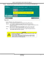
Step 33.
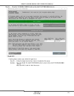
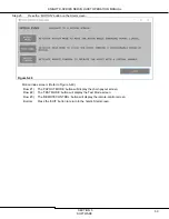
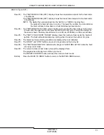
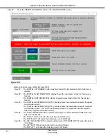
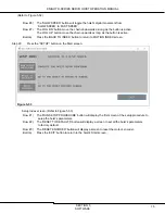
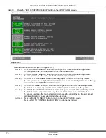
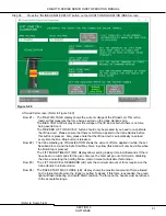
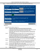
Press the “PHYSICAL LIMITS SETUP” button on the HOIST CONFIGURATION INDEX screen.
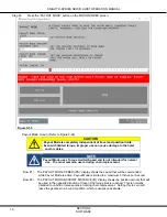
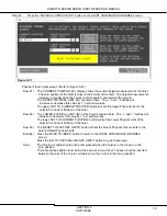
Figure 5-57
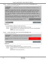
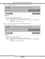
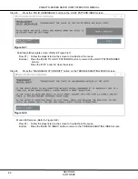
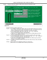
Physical Travel Limits screen: (Refer to Figure 5-57)
Row #1) The ‘CURRENT POSITION (IN)’ display shows the vertical height measurement of the hoist.
The zero position of the hoist is close to the bottom of the hoist. The height measurements
increase in magnitude as the hoist’s control handle move towards the ground.
The ‘UPPER PHYSICAL LIMIT (IN)’ is entered here. The “+” and “-“ buttons will
increase or decrease this value by 1” per button-press.
The upper ‘SET TO CURRENT POSITION’ button will set the Upper Physical Limit of the
hoist to the Current Position of the hoist.
Row #2) The ‘LOWER PHYSICAL LIMIT (IN)’ of the hoist is entered here. The “+” and “-“ buttons will
increase or decrease this value by 1” per button-press.
The lower ‘SET TO CURRENT POSITION’ button will set the Lower Physical Limit of the
hoist to the Current Position of the hoist.
Row #3) The ‘RESET TO FACTORY LIMITS’ button will set the hoist’s Physical Travel Limits to the
hoist’s Default Physical Limits.
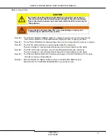
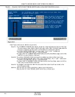
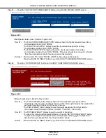
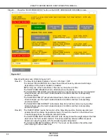
Buttons) Press the ‘BACK TO INDEX’ button to return to the HOIST CONFIGURATION INDEX
screen.
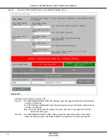
Press the ‘GO TO PHYSICAL WEIGHT LIMITS’ button to go to that screen.
Note)
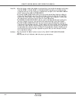
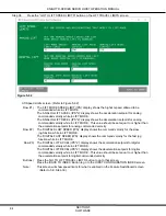
The 19-pin coil cable should not be compressed when the hoist is in the full up or at its
zero position.
There should be addition room below the servo so a two-inch (2”) spacer could be inserted
between the coils of the 19-pin coil cable when the hoist is in the full up position.

