KNIGHT D-SERIES SERVO HOIST OPERATION MANUAL
SECTION 2
INSTALLATION
5
A. Introduction
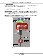
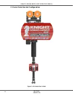
Prior to installing and operating the Knight Servo Hoist, all operators using this device should be familiar with
the main components of the lifting system. (Refer to Figure 2-1)
Servo Hoist:
The Servo Hoist assembly is a powered lifting device. The upper drive assembly contains the
servo motor with holding brake, gearbox, servo drive, power contactor, 24 VDC Power Supply, regen board,
chain bucket, chain guide assembly, and AC Plug.
Coiled Cable Assembly:
In most cases, a 19-pin coil cable carries signals from the control handle to the
Servo Hoist. Some examples are: Analog load cell voltages, digital inputs and outputs including direction
commands, Lift Mode, Float Mode, and Run-Stop signals. In some cases, a 19-pin straight cable carries
some or all of these signals to the Servo Hoist.
Control Handle:
The main interface between the operator and the lifting device. The handle can be an
inline handle, a fixture handle, or a discrete up / down handle.
Figure 2-1
Trolley or Universal
Adapter Plate
Safety
Cable
19-pin
Coil Cable
Chain Nest
Control Handle
(Inline)
Load Shackle
Location
Servo Hoist


