KNIGHT D-SERIES SERVO HOIST OPERATION MANUAL
SECTION 5
SOFTWARE
78
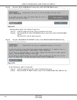
Step 32.
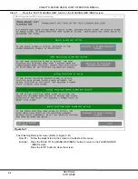
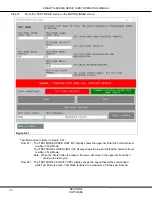
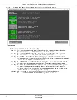
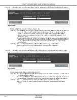
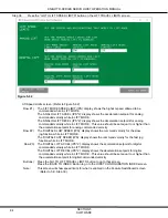
Press the “GO TO HOIST CONFIGURATION” button on the POSITION CALIBRATION screen.
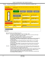
Figure 5-56
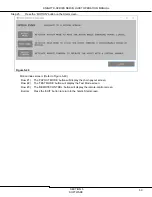
Hoist Configuration Index screen: (Refer to Figure 5-56)
Row #1) The ‘PHYSICAL LIMITS SETUP’ button will display screens to setup the hoist’s physical
motion limits.
Row #2) The ‘INLINE HANDLE SETUP’ button will display screens to calibrate the lift load cell,
setup Lift Mode, and set respective limits.
Row #3) The ‘FLOAT LOAD CELL SETUP’ button will display screens to calibrate the float load cell,
setup Float Mode, and set respective limits.
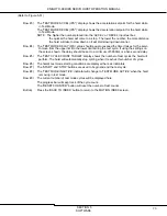
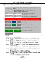
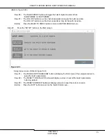
If FLOAT MODE has been disabled on the FEATURE SWITCHBOARD screen, this button
will display to the ‘FLOAT LOAD CELL’ screen and the respective FLOAT MODE screens
will be accessible via the “Workspace” tab.
Row #4) The ‘FIXTURE WEIGHT SETUP’ button will display a screen to set a connected fixture.
Row #5) The ‘SLOW ZONE SETUP’ button will display a screen to enable and setup slow zones.
Buttons) Press the ‘GO TO POSITION CALIBRATION’ button to return to that screen.
Press the ‘BACK TO INDEX’ button to return to the SETUP INDEX screen.

