43
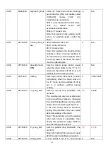
Kt[Nm/Arms]*100
d4.14
64101010
Jr_Motor
Indicates the rotor inertia of motors
Jr[kgm^2]*1 000 000
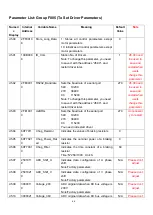
d4.15
64101110
Brake_Duty_Cycle
Indicates the duty cycle of contracting brakes
0~2500[0…100%]
d4.16
64101210
Brake_Delay
Indicates the delay time of contracting brakes
Default value: 150 ms
d4.17
64101308
Invert_Dir_Motor
Indicates the rotation direction of motors
d4.18
64101610
Motor_Using
Current using motor type.
PC Software
Numeric Display
Model
"K0"..........................
.304.B…………....SMH60S-0020-30
"K1"..........................
.314.B…………….SMH60S-0040-30
"K2".........................
..324.B…………….SMH80S-0075-30
"K3".........................
..334.B…………….SMH80S-0100-30
"K4".........................
..344.B…………….SMH110D-0105-20
"K5".........................
..354.B…………….SMH110D-0125-30
"K6".........................
..364.B………….....SMH110D-0126-20
"K7"………………......374.B…………….SMH110D-0126-30
"
K8"…………………...384.B..................SMH110D-0157-30
"K9"...........................
.394.B…………....SMH110D-0188-30
―KB"…………………...424.B…………....SMH130D-0105-20
―KC"…………………...434.B…………….SMH130D-0157-20
―KD"…………………...444.B…………….SMH130D-0210-20
―KE"…………………...454.B……………..SMH150D-0230-20
"S0"…………………...305.3………….130D-0105-20AAK-2LS
"S1"............................315.
3…………..130D-0157-20AAK-2LS
"S2"…………………...325.3………….130D-0157-15AAK-2LS
"S3"............................335.
3………….130D-0200-20AAK-2HS
"S4"............................345.
3…………..130D-0235-15AAK-2HS
"F8"…………………...384.6…………..85S-0045-05AAK-FLFN
"E0"...........................
..304.5………………..SME60S-0020-30
"E1"...........................
..314.5………….........SME60S-0040-30
"E2"..............................324.5
………………..SME80S-0075-30
d4.19
64101410
Motor_Num
The same function as d4.01.But it is specially used for
configuring motor at the first time,and needn
’
t restart driver.
Содержание CD2S Series
Страница 7: ...7...
Страница 8: ...8 1 3 3 Power Brake and Encoder cable of Motors...
Страница 12: ...12 Fig 2 3 Installation direction...
Страница 15: ...15 3 1 2 Wiring Diagram Fig 3 1 Wiring diagram of CD2S driver...
Страница 16: ...16 3 1 3 X1 interface of CD2S Driver Fig 3 2 X1 interface Fig 3 3 Wiring diagram of X1 interface...
Страница 23: ...23 Fig 4 3 Separate regulation of bits...
Страница 82: ...82...
Страница 96: ...96 8 4 Debugging example 8 4 1 Oscilloscope 1 Enter oscilloscope 2 Parameters for Oscilloscope...
Страница 98: ...98 In Auto Reverse mode Kvp 110...
Страница 100: ...100 The oscilloscope is as following max following error is 69 inc Fig 2 Kpp 30 Vff 100...
Страница 101: ...101 The oscilloscope is as following max following error is 53 inc Fig 3 Kpp 30 Vff 50...
Страница 102: ...102 The oscilloscope is as following max following error is 230 inc...


