49
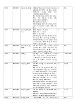
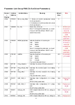
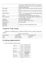
400.0: Activate command
Note:DinX_Function (X ranges from 1 to 7) is used to define the functions of digital input ports. User can
freely define the functions of the digital input ports according to actual applications.
Table 6-9 Meaning of defined functions of digital input signals
Function
Meaning
Disable
Used to cancel the function of this digital input.
Driver enable
By default, the driver enable signal is valid, and the motor shaft is locked.
Driver fault reset
Signals on the rising edge are valid, and alarms are cleared.
Operation mode control
To switch between two operation modes.
You can freely determine the operation modes corresponding to valid signals
and invalid signals by performing settings through d3.16 Din_Mode0 (choose
0 for operation mode) of Group F003 and Din_Mode1 (choose 1 for operation
mode) of Group F003.
P control for velocity loop
Indicates the control on stopping integration in velocity loop. The control is
applied in the occasion where high-speed system stop occurs, but
overshooting is not expected.
Note: In the ―-3‖ mode, if the signal is valid, fixed errors occur between the
actual speed and target speed.
Position positive limit
Indicates the limit of forward running of motors (normally closed contact by
default).
By default, the driver regards position positive limits as valid, and polarity can
be modified to adjust to normally open switches.
Position negative limit
Indicates the limit of inverted running of motors (normally closed contact by
default).
By default, the driver regards position negative limits as valid, and polarity can
be modified to adjust to normally open switches.
Homing signal
To find origins of motors.
Reverse speed demand
To reverse the target speed in the speed mode ("-
3" or ―3‖).
Internal speed control 0
To control internal multiple speeds.
Note: For details, see Section 7.5 Internal Multi-Speed Control.
Internal speed control 1
Internal speed control 2
Internal position control 0
To control internal multiple positions.
Note: For details, see Section 7.4 Internal Multi-Position Control.
Internal position control 1
Internal position control 2
Multi Din 0
To switch multiple electronic gear
Multi Din 1
Multi Din 2
Gain switch 0
To switch multiple gain parameters(P-gain of velocity loop,i-gain of velocity
loop,p-gain of position loop)
Gain switch 1
Quick stop
When the signal is valid, the motor shaft releases.
After the signal is removed, the driver requires re-enabling.
Start homing
When the rising edge of the signal is detected,it will start homing command.
Содержание CD2S Series
Страница 7: ...7...
Страница 8: ...8 1 3 3 Power Brake and Encoder cable of Motors...
Страница 12: ...12 Fig 2 3 Installation direction...
Страница 15: ...15 3 1 2 Wiring Diagram Fig 3 1 Wiring diagram of CD2S driver...
Страница 16: ...16 3 1 3 X1 interface of CD2S Driver Fig 3 2 X1 interface Fig 3 3 Wiring diagram of X1 interface...
Страница 23: ...23 Fig 4 3 Separate regulation of bits...
Страница 82: ...82...
Страница 96: ...96 8 4 Debugging example 8 4 1 Oscilloscope 1 Enter oscilloscope 2 Parameters for Oscilloscope...
Страница 98: ...98 In Auto Reverse mode Kvp 110...
Страница 100: ...100 The oscilloscope is as following max following error is 69 inc Fig 2 Kpp 30 Vff 100...
Страница 101: ...101 The oscilloscope is as following max following error is 53 inc Fig 3 Kpp 30 Vff 50...
Страница 102: ...102 The oscilloscope is as following max following error is 230 inc...


