30
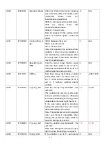
SMH60S-0040-30xxx-3LKH K1/314B
EA02
Command Type
The command type affects controller-internal interface settings, the initial
operation mode after power on and the default settings for DIN- and OUT
functions (refer to table 4-3).
0: CW/CCW pulse train mode
Operation mode = -4
1: P/D pulse train mode
Operation mode = -4
2: A/B phase control master / slave mode Operation mode = -4
6: Analog velocity mode by AIN1
Operation mode = -3
7: Analog velocity mode by AIN2
Operation mode = -3
8: Communication
9: Position table mode
Operation mode = 1
1
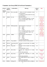
EA03
Gear
Factor
Numerator
Used when EA02 is set to 0-2.
By default, the display shows the values in decimal format. If the number is
greater than 9999, the display is in hexadecimal format.
1000
EA04
Gear Factor
Denominator
1000
EA05
Analog
Speed
Factor
Used when EA02 is set to 6 or 7.
The relationship between analog input voltage and motor velocity the unit of
measure is rpm/V.
For controller use with standard KINCO-AS motors, the maximum value is
374, the maximum velocity is 3740rpm/10v/.
For more details see chapter 9.3 (d3.29).
300
EA06
1.Load type
2.Application
3.Limit switch
4. Alarm output
polarity
The meaning of each digit of the LED display from right to left.
(1) Load type, influences the control loop.
0: No load
1: Belt drive
2: Ball screw
(2) Application, influences the control loop.
0: P2P
1: CNC
2: Master / slave mode
(3) Limit switch.
0: Controller default
1: Delete the limit switch function
(4) Polarity of OUT5
0: Normally closed contacts
1: Normally open contacts
1001
EA07
Homing method
Refer to chapter 6.6
0
EA00
Save
Parameters
Write ―1‖ to save control and motor parameters.
Write ―2‖ to save control and motor parameters and reboot the servo.
Write ―3‖ to reboot the servo.
Write ―10‖ to initialize the control parameters.
Notice:
/
Содержание CD2S Series
Страница 7: ...7...
Страница 8: ...8 1 3 3 Power Brake and Encoder cable of Motors...
Страница 12: ...12 Fig 2 3 Installation direction...
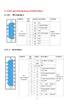
Страница 15: ...15 3 1 2 Wiring Diagram Fig 3 1 Wiring diagram of CD2S driver...
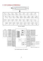
Страница 16: ...16 3 1 3 X1 interface of CD2S Driver Fig 3 2 X1 interface Fig 3 3 Wiring diagram of X1 interface...
Страница 23: ...23 Fig 4 3 Separate regulation of bits...
Страница 82: ...82...
Страница 96: ...96 8 4 Debugging example 8 4 1 Oscilloscope 1 Enter oscilloscope 2 Parameters for Oscilloscope...
Страница 98: ...98 In Auto Reverse mode Kvp 110...
Страница 100: ...100 The oscilloscope is as following max following error is 69 inc Fig 2 Kpp 30 Vff 100...
Страница 101: ...101 The oscilloscope is as following max following error is 53 inc Fig 3 Kpp 30 Vff 50...
Страница 102: ...102 The oscilloscope is as following max following error is 230 inc...

