39
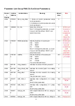
Parameter List: Group F003 (To Set Input/Output & Pattern Operation
Parameters)
Numeric
Display
Internal
Address
Variable Name
Meaning
Default
Value
Range
d3.00
2FF00108
Store_Loop_Data
1: Stores all control parameters except
motor parameters
10: Initializes all control parameters except
motor parameters
0
N/A
d3.01
20100310
Din1_Function
000.1: Driver enable
000.2: Driver fault reset
000.4: Operation mode control
000.8: P control for velocity loop
001.0: Position positive limit
002.0: Position negative limit
004.0: Homing signal
008.0: Reverse speed demand
010.0: Internal speed control 0
020.0: Internal speed control 1
800.1: Internal speed control 2
040.0: Internal position control 0
080.0: Internal position control 1
800.2: Internal position control 2
800.4 Multi Din 0
800.8 Multi Din 1
801.0 Multi Din 2
802.0 Gain switch 0
804.0 Gain switch 1
100.0: Quick stop
200.0: Start homing
400.0: Activate command
000.1
N/A
d3.02
20100410
Din2_Function
000.2
N/A
d3.03
20100510
Din3_Function
000.4
N/A
d3.04
20100610
Din4_Function
000.8
N/A
d3.05
20100710
Din5_Function
001.0
N/A
d3.06
20100810
Din6_Function
002.0
N/A
d3.07
20100910
Din7_Function
004.0
N/A
d3.08
20100110
Dio_Polarity
Sets IO polarity
0
N/A
d3.09
2FF00810
Dio_Simulate
Simulates input signals, and enforce output
signals for outputting
0
N/A
d3.10
20000008
Switch_On_Auto
Automatically locks motors when drivers
are powered on
0: No control
1: Automatically locks motors when drivers
are powered on
0
0~1
d3.11
20100F10
Dout1_Function
000.1: Ready
000.2: Error
000.4: Position reached
000.8: Zero velocity
000.1
N/A
d3.12
20101010
Dout2_Function
000.2
N/A
d3.13
20101110
Dout3_Function
00a.4
N/A
d3.14
20101210
Dout4_Function
000.8
N/A
Содержание CD2S Series
Страница 7: ...7...
Страница 8: ...8 1 3 3 Power Brake and Encoder cable of Motors...
Страница 12: ...12 Fig 2 3 Installation direction...
Страница 15: ...15 3 1 2 Wiring Diagram Fig 3 1 Wiring diagram of CD2S driver...
Страница 16: ...16 3 1 3 X1 interface of CD2S Driver Fig 3 2 X1 interface Fig 3 3 Wiring diagram of X1 interface...
Страница 23: ...23 Fig 4 3 Separate regulation of bits...
Страница 82: ...82...
Страница 96: ...96 8 4 Debugging example 8 4 1 Oscilloscope 1 Enter oscilloscope 2 Parameters for Oscilloscope...
Страница 98: ...98 In Auto Reverse mode Kvp 110...
Страница 100: ...100 The oscilloscope is as following max following error is 69 inc Fig 2 Kpp 30 Vff 100...
Страница 101: ...101 The oscilloscope is as following max following error is 53 inc Fig 3 Kpp 30 Vff 50...
Страница 102: ...102 The oscilloscope is as following max following error is 230 inc...


