20
real time.
3. Indicates the earliest error when history records of errors (F007) are displayed.
③
1. Indicates a data display format when parameters are displayed and adjusted in real time. If it is
on, it indicates the data is displayed in hexadecimal; otherwise it indicates the data is displayed
in decimal.
2. Indicates the latest error when the history records of errors (F007) are displayed.
④
1. If it is on, it indicates that internal data is currently displayed.
2. If it flickers, it indicates that the power part of the driver is in the working status.
MODE
1. Switches basic menus.
2. During the adjustment of parameters, short presses the key to move the bit to be adjusted, and
long presses the key to return to the previous state.
▲
Presses ▲ to increase set values; long presses ▲ to increase numbers promptly.
▼
Presses ▼ to decrease set values; long presses ▼ to decrease numbers promptly.
ENTER
1. Enters the selected menu by pressing this key.
2. Keeps current parameters in the enabled status.
3. Confirms input parameters after parameters are set.
4. Long presses this key to switch to higher/lower 16 bits when internal 32-bit data is displayed in
real time.
P..L
Activates position positive limit signals.
n..L
Activates position negative limit signals.
Pn.L
Activates position positive/negative limit signals.
Overall
Flicking
Indicates that an error occurs on the driver, and is in the alarm state.
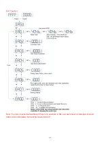
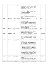
If the parameter adjusting display mode is featured by the decimal system:
When the units place is flickering, pres
s ▲ to add 1 to the current value; press ▼ to deduct 1 from the
current value. When the tens place is flickering, press ▲ to add 10 to the current value; press ▼ to deduct 10
from the current value. When the hundreds place is flickering, press ▲ to add 100 to the current value; press ▼
to deduct 100 from the current value. When the thousands place is flickering, press ▲ to add 1000 to the current
value; press ▼ to deduct 1000 from the current value.
If the parameter adjusting display mode is featured by the hexadecimal system:
When the units place is flickering, press ▲ to add 1 to the current value; press ▼ to deduct 1 from the
current value. When the tens place is flickering, press ▲ to add 0X10 to the current value; press ▼ to deduct
0X10 from the current
value. When the hundreds place is flickering, press ▲ to add 0X100 to the current value;
press ▼ to deduct 0X100 from the current value. When the thousands place is flickering, press ▲ to add 0X1000
to the current value; press ▼ to deduct 0X1000 from the current value.
When adjusting decimal parameters, the display mode is automatically switched to the hexadecimal system
if the data is greater than 9999 or less than -9999. In this case, the 3
rd
decimal point from left to right is
highlighted.
Содержание CD2S Series
Страница 7: ...7...
Страница 8: ...8 1 3 3 Power Brake and Encoder cable of Motors...
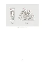
Страница 12: ...12 Fig 2 3 Installation direction...
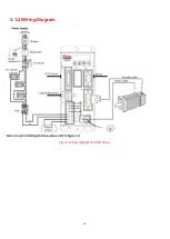
Страница 15: ...15 3 1 2 Wiring Diagram Fig 3 1 Wiring diagram of CD2S driver...
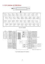
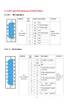
Страница 16: ...16 3 1 3 X1 interface of CD2S Driver Fig 3 2 X1 interface Fig 3 3 Wiring diagram of X1 interface...
Страница 23: ...23 Fig 4 3 Separate regulation of bits...
Страница 82: ...82...
Страница 96: ...96 8 4 Debugging example 8 4 1 Oscilloscope 1 Enter oscilloscope 2 Parameters for Oscilloscope...
Страница 98: ...98 In Auto Reverse mode Kvp 110...
Страница 100: ...100 The oscilloscope is as following max following error is 69 inc Fig 2 Kpp 30 Vff 100...
Страница 101: ...101 The oscilloscope is as following max following error is 53 inc Fig 3 Kpp 30 Vff 50...
Страница 102: ...102 The oscilloscope is as following max following error is 230 inc...

