background image

40

Shooting

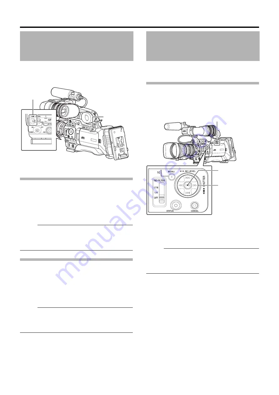
This function electrically boosts the light sensitivity when 
there is insufficient illumination on the object. You can set the 
gain of the video amplifier according to the brightness of the 
object. Select the setting mode according to your shooting 
conditions.

Fixed Gain Mode (Manual Gain Switching)

You can select the gain of the video amplifier using the 
[GAIN] switch on the camera recorder.
The default positions of the switch are as follows.

Memo :                                                                                 

The gain value of each position can be set to 

A

ALC

B

 and 

within the range of 

A

0dB

B

 to 

A

18dB

B

 (in increments of 

3

 dB) 

in the menu. Increasing the sensitivity causes the screen to 


appear grainier. (

A

Page 79)

Automatic Gain Mode (Automatic Gain 
Adjustment)

Set the [FULL AUTO] switch on the camera recorder to 

A

ON

B


to enter Automatic gain Level Control (

A

ALC

B

 fixed). The 

gain of the video amplifier is automatically set according to 
the brightness of the object.
In this case, the [GAIN] switch on the camera recorder is 
disabled.

Memo :                                                                                 

When [Gain] in the [Camera Function] 

B

 [FULL AUTO] 

menu is set to 

A

SW Set

B

, you can switch the gain with the 

[GAIN] switch even if the [FULL AUTO] switch on the 


camera recorder is set to 

A

ON

B

. (

A

Page 81)

You can change the shutter speed (time for each shooting 
frame) using the electronic shutter function. Electronic 
shutter can be adjusted manually or automatically.

Fixed Shutter Mode (Manual Shutter 
Switching)

Use the Set button (

R

) to switch between the shutter modes 

and the cross-shaped button (

JK

) to switch between the 

speeds.

Switching Shutter Mode

Press the Set button (center of the cross-shaped button) to 
turn ON/OFF the shutter.

Memo :                                                                                 

When the shutter is ON, 

A

Step

B

A

Variable

B

, or 

A

EEI

B


(Extended Electric Iris, i.e. Automatic Shutter mode) may 
be selected using [Shutter] in the [Camera Function] 


menu. 

A

Step

B

 is the factory default. (

A

Page 78)

Setting Gain

[L] : 0 dB (No electrical boosting.)
[M] : 9 dB (Boosts sensitivity by about 2.8 times. )
[H] : 18 dB (Boosts sensitivity by about 8 times. )

[GAIN] Selection 

Switch

[FULL AUTO] 
Switch

Setting the Electronic 
Shutter

Cross-Shaped Button 
(

JK

)

[FULL AUTO] Switch

Set Button (

R

)

Содержание GY-HM790U

Страница 1: ...y Retain this information for future reference Model No GY HM790U GY HM790CHU Serial No Please read the following before getting started Thank you for purchasing this JVC product Before operating this unit please read the instructions carefully to ensure the best possible performance In this manual each model number is described without the last letter U E which means the shipping destination U fo...

Страница 2: ...it form the wall outlet and disconnect the antenna or cable system This will prevent damage to the product due to lightning and power line surges These are general IMPORTANT SAFEGUARDS and certain items may not apply to all appliances 3 All warnings on the product and in the operating instructions should be adhered to FOR USA 14 Never push objects of any kind into this appliance through cabinet sl...

Страница 3: ...ATTENTION POUR EVITER TOUT RISQUE D ELECTROCUTION NE PAS OUVRIR LE BOITER AUCUNE PIECE INTERIEURE N EST A REGLER PAR L UTILISATEUR SE REFERER A UN AGENT QUALIFIE EN CAS DE PROBLEME Le symbole de l éclair àl intérieur d un triangle équilatéral est destiné à alerter l utilisateur sur la présence d une tension dangereuse non isolée dans le boîtier du produit Cette tension est suffisante pour provoque...

Страница 4: ...hrter Kunde sehr geehrte Kundin dieses Gerät stimmt mit den gültigen europäischen Richtlinien und Normen bezüglich elektromagnetischer Verträglichkeit und elektrischer Sicherheit überein Die europäische Vertretung für die Victor Company of Japan Limited ist JVC Technical Services Europe GmbH Postfach 10 05 04 61145 Friedberg Deutschland Information for Users on Disposal of Old Equipment European U...

Страница 5: ...V ...

Страница 6: ... Function 37 Selecting System Definition File Format and Video Format 38 Selecting the Aspect Ratio of SD Videos 39 Adjusting the Iris 39 Setting Gain 40 Setting the Electronic Shutter 40 Adjusting the White Balance 42 Adjusting the White Shading 44 Setting the ND Filter 45 Adjusting Audio Input Settings and Recording Level 46 Setting Audio Input 46 Adjusting Audio Recording Level 46 Audio Monitor...

Страница 7: ...as Black Stretch Compress Function 118 Configuring Setup Files 119 Saving Setup Files 120 Loading a Setup File 121 Resetting Setup Files 121 Connecting External Devices Connecting an External Monitor 122 IEEE1394 Connection 123 Backup Recording 124 Input of Composite Video Signals from External Device GY HM790CHU GY HM790U only 125 Input of External Synchronizing Signal Genlock 126 Displaying Retu...

Страница 8: ...s 1440x1080 and 1920x1080 full resolution in the 1080 format Adoption of MPEG 2 Long GOP for Easy Editing Shortens editing and output time by adopting MPEG 2 codec which puts less stress on the editing computer High Resolution via Triplex Offset 2 5k x 1 4k pixels are generated with the Triplex Offset and a high resolution of more than 900 horizontal lines and 1000 diagonal lines is achieved using...

Страница 9: ... unit during recording the tuner could pick up noise 䡵 Avoid using or placing this unit in the following places Places subject to extreme heat or cold Places with excessive dirt or dust Places with high humidity or moisture Places subject to smoke or vapor such as near a cooking stove Places subject to strong vibrations or unstable surfaces In a parked car under direct sunlight or near a heater fo...

Страница 10: ...d to burns and fires 䡵 Do not turn off the POWER switch or remove the power cable during recording or playback 䡵 The camera recorder may not show stable pictures for a few seconds immediately after the power is turned on but this is not a malfunction 䡵 When the video signal output terminals are not in use put on the covers to prevent damage to the terminals 䡵 Do not drop this unit or subject it to...

Страница 11: ... on the SDHC cards 䡵 Do not use pencils or ballpoint pens to write on the SDHC cards Always use oil based pens 䡵 If you format initialize the SDHC card all data recorded on the card including video data and setup files will be deleted 䡵 You are recommended to use cards that are formatted initialized on this camera recorder The SDHC card may be damaged if the camera recorder is not operated correct...

Страница 12: ...de USB Mode USB Mass Storage Class Camera Mode IEEE1394 Mode SD Card Mode Thumbnail Display Playback Playback Pause Fast Forward Rewind Clip Jump CAM MEDIA Selection Button CAM MEDIA Selection Button CAM MEDIA Selection Button Playback Button Stop Button Connection disabled on PC CAM MEDIA Button USB Connection When the confirmation to change to USB mode appears and Change is selected Playback But...

Страница 13: ...ra recorder to detect the IEEE1394 terminal connection in advance by turning on the power of the connected equipment in Camera mode Once the camera recorder is in IEEE1394 mode the playback images of the connected equipment are displayed However if the IEEE1394 connection is not recognized such as when the power of the IEEE1394 connected equipment is not turned on the camera recorder will switch t...

Страница 14: ... set to APRESETB you can switch the color temperature of the preset white balance E Lens Lock Lever A Page 21 F MONITOR SELECT Audio Monitor Selection Switch A Page 46 G DISPLAY Display Button A Page 30 H CAM MEDIA Camera Media Mode Selection Button A Page 8 I FULL AUTO Full Auto Shooting FAS Switch A Page 81 J Monitor Speaker Cheek Pad A Page 27 K Shoe For mounting separately sold lights and acce...

Страница 15: ...tion Switch A Page 46 V Viewfinder Connector 20 pin A Page 21 W Accessory Mounting Screw Hole x2 X FOCUS ASSIST Focus Assist Button A Page 37 Y Record Button Lock Switch Set the switch toward the lens to lock the REC trigger button Z Memo The REC trigger button A Page 12 K at the side control panel on the right of the camera recorder is not locked Z REC Rec Trigger Button Recording Start Stop Star...

Страница 16: ...he LCD monitor and viewfinder Wait for 5 seconds or more to turn on the power again K REC Rec Trigger Button Recording Start Stop Starts stops recording The REC trigger button A Page 11 Z on top and the REC trigger button A Page 16 of the lens are interlocked with this button Memo When 1394 Rec Trigger in the Others menu is set to ASplitB this button becomes the recording start stop button of the ...

Страница 17: ...g the position of the viewfinder E to the left or right B Eyepiece Focus Ring For adjusting the visibility C Viewfinder Eyepiece Lock Ring For loosening the ring and adjusting the eyepiece position of the viewfinder to the front or back D Viewfinder E Eyepiece Prevents external light from entering the viewfinder screen and cameraman s vision LCD Monitor A LCD Monitor A Page 28 B LCD PEAKING LCD Co...

Страница 18: ...UTPUT CH 1 CH 2 Audio Output Terminal RCA Output terminal for audio signals Input audio signals are output during Camera mode Playback audio signals are output during Media mode Audio from input audio signals is output during HD DV signal IEEE1394 input Memo Alarm tone is not output M INT EXT IEEE1394 Interface Terminal Switch A Page 123 For selecting a valid IEEE1394 interface terminal N Shoulder...

Страница 19: ...r If the shoulder belt is not properly attached the camera recorder may fall and cause injuries Check the instruction manual provided with the shoulder belt before using B Accessory Connection Terminal Terminal for connecting a KA MR100G Memory Recorder sold separately or KA M790G Multicore Remote Adapter sold separately unit Memo When using this terminal make sure that the Battery Adapter C is re...

Страница 20: ... set too fast opening closing of the iris becomes unstable and hunting may occur Readjust the speed in this case K Filter Built In Screw A transparent or UV filter for lens protection can be installed inside the lens hood from the front Filters for various effects can also be used Installable filter types L Zoom Servo Connector For connecting a zoom servo unit sold separately M ZOOM Zoom Switch N ...

Страница 21: ...Composite Cable BNC Audio Cable RCA pin IEEE1394 Cable 4P 6P Monitor VTR Non linear Editing System BR HD50U E For GY HM790CHE GY HM790E Anton Bauer Battery Dionic90 Remote Control Unit RM LP25U RM LP55U RM LP57U IDX Battery Charger External Recording Device Component Cable BNC Battery Adapter Monitor IDX Battery Endura Anton Bauer Battery Charger For GY HM790CHU GY HM790U SDI Cable BNC GY HM790CHU...

Страница 22: ...of the STATUS button STATUS 0 B 1 B 2 B 3 B 4 B 0 The STATUS 0 screen is skipped in the AUX mode U model only LCD monitor display The display switches between the 5 screen types with every press of the STATUS button STATUS 0 B 1 B 2 B 3 B 4 B 0 Press the DISPLAY button to switch to the enlarged status display screen A Page 19 The STATUS 0 screen is skipped in the AUX mode U model only Displays on ...

Страница 23: ...Monitor You can enlarge and display only the characters of the status screen on the LCD monitor Camera mode only 1 Set LCD VF in the LCD VF menu to AOnB A Page 88 2 Press the DISPLAY button while the LCD screen is displayed The display switches between the same display as the viewfinder and the enlarged display with every press of the button Memo During enlarged display of the status on the LCD mo...

Страница 24: ...y will return to STATUS 0 screen and alarm will be displayed A Page 134 Error Displays and Actions Zebra Pattern Display Two types of zebra patterns that indicate the luminance level of the video image can be displayed on this camera recorder You can set the luminance levels for displaying the two types of zebra patterns A Page 54 Setting Zebra Pattern Memo Use the ZEBRA ON OFF switch in front to ...

Страница 25: ...m power supply 1Turn the knob on the microphone holder anticlockwise to loosen and open the microphone holder 2Place the microphone in the microphone holder 3Turn the knob on the microphone holder clockwise to secure the microphone 4Connect the microphone cable to the INPUT1 or INPUT2 terminal 5Pin the microphone cable to the clamp 6Make sure to perform the correct settings for the phantom microph...

Страница 26: ...hen the power is disconnected the battery gradually discharges The battery will be totally discharged if left unused for 3 months and the date time and time code data will be reset When this happens set the POWER switch to AONB to display the Initial Setting screen then set the date time A Page 26 Setting the Clock Initial Setting Recommended Batteries U model Dionic90 Anton Bauer E model Endura H...

Страница 27: ... battery will not be attached correctly 2 Slide the battery toward the SDHC card cover side panel until it snaps into place 䡵 Detaching the Battery Press down the release lever and slide the battery toward you to detach it from the camera recorder Attaching the Battery GY HM790CHE GY HM790E Use the Endura HL9 IDX battery 1 Attach the battery Face the terminal downward and attach the V mount of the...

Страница 28: ...ttery power and time are low Precautions for Batteries Store the battery in a cool and dry place when not in use Do not expose the battery to high temperatures such as in a car under direct sunlight This will cause battery leakage and shorten the battery life Operating time is shortened if the battery terminal is dirty If the operating time shortens drastically even after charging the battery may ...

Страница 29: ...CD monitor Memo System Definition is fixed at ASD DV B in the AUX mode A Page 56 䡵 Media Mode SD Card Mode This mode allows you to play back or delete clips recorded on the SDHC card When a playable SDHC card is inserted the thumbnail or playback screen is output on the viewfinder and LCD monitor 䡵 Media Mode IEEE1394 Input Mode This mode allows you to check IEEE1394 input signals When playable IE...

Страница 30: ...H I and select the setting item B Change the values with the cross shaped button JK 3 Press the Set button after setting is complete The clock is set to 0 seconds of the input date time Memo The configured date time data can be displayed on the LCD monitor and viewfinder and be recorded to the SDHC card The value of the year can be set in the range of A2000B to A2099B Changing the Time after Initi...

Страница 31: ...hour 12 hour display 24hour 24 hour display C Press the Set button R Date Time Display in Different Operation Modes The monitor speaker can be rotated 180 degrees Adjust according to the position of your ear Memo Adjust the volume of the monitor speaker with the MONITOR level adjustment knob at the side control panel on the right of the camera recorder Various warning alarm tones may also be outpu...

Страница 32: ... both the telephoto and wide angle positions 10 Tighten and secure the lock screw of the back focus ring Adjusting the LCD Monitor You can change the angle and brightness of the LCD monitor screen according to your usage condition Changing the brightness of the screen will not affect the recorded images 䡵 Adjusting the Angle of the LCD Monitor 1 Slide the LCD lock release knob to open the LCD moni...

Страница 33: ...der is used on this camera recorder in order to provide an accurate focusing environment Due to the characteristic of the display device colors may appear on the images when you blink your eyes This is not a malfunction It does not affect the recorded images SDI output or component output 䡵 Adjusting the Angle Adjust the position and angle of the viewfinder 䡵 Adjusting the Visibility Turn the eyep...

Страница 34: ...indicated as below Memo Press and hold the DISPLAY button for 2 seconds to turn ON OFF the LCD monitor screen The function to turn ON OFF the LCD monitor screen by pressing the DISPLAY button can be canceled by opening closing or rotating the LCD monitor The viewfinder screen is always displayed These are indicator lamps for recording and warning The operation changes according to the menu setting...

Страница 35: ... from a PC the recordable time may be shorter or data may not be properly recorded 䡵 Write Protect Switch on the SDHC Card A Slide the write protect switch upward to enable writing or deleting B Slide the write protect switch downward to prevent writing or deleting Images in the card are protected Menu Setting Tally System Int Ext Studio Front Tally Back Tally 1 Off On Blin k On Blink On Blink Cam...

Страница 36: ... green or not before you turn off the power or remove the SDHC card If you mistakenly remove the card when it is being accessed reinsert the card only after the status indicator goes off The SDHC card may not be recognized if you insert and remove the card within a short time When this happens remove the card and wait for a few seconds before you reinsert Switching SDHC cards When both card slots ...

Страница 37: ...d and press the Set button R 3 The status of the selected SDHC card appears 4 Select Format and press the Set button R 5 Formatting starts 6 Formatting is complete ACompleteB appears when formatting is complete Memo If you do not want to format the card select Cancel or press the CANCEL button to return to the previous screen If you remove the SDHC card during formatting AFormat Error B appears an...

Страница 38: ...mplete ACompleteB appears and the camera recorder returns to the Restore Media screen When no media that requires restoring is inserted the camera recorder returns to the Media menu screen Note Restore Media can only be selected in Camera mode However it cannot be selected while the camera recorder is recording Select Restore Media in Camera mode when the camera recorder is not recording Restore M...

Страница 39: ...er Example Clip Name Prefix any 4 alphanumeric characters This is set to AxxxGB AxxxB denotes the last 3 digits of the serial number by default Memo Before recording starts you can set any characters for the clip name prefix by using Main Menu B Record Set menu B Clip Set B Clip Name Prefix A Page 76 Changes cannot be made after recording 䡵 Recorded Clips This camera recorder uses FAT32 File Syste...

Страница 40: ...ng Audio Input Settings and Recording Level A Page 46 2 Press the REC button to start recording to the SDHC card There are two REC buttons on the camera recorder and one on the lens Any of the REC buttons can be used to start stop recording by default During recording the front and back tally lamps light up in red Memo Tally lamps can be turned off with Front Tally Back Tally in the Others menu A ...

Страница 41: ...wer to enable easier focusing A Page 89 The AACCU FocusB function switches automatically to AOffB after about 10 seconds Select the display color in Main Menu B LCD VF B Shooting Assist B Color A Page 89 The VF PEAKING knob and LCD PEAKING button do not function when Focus Assist is activated 䡵 Assigning Focus Assist function to the RET button on the lens You can assign the Focus Assist function t...

Страница 42: ... the settings of System Definition File Format and Camera Resolution The recording bit rate is 35 Mbps VBR when AHQB is selected and 18 3 Mbps 1080i is 25 Mbps CBR when ASPB is selected 䡵 List of Formats The following is a list of file formats and video formats that can be selected on this camera recorder 䡵 When System Definition is set to AHD MPEG2 B Selecting System Definition File Format and Vi...

Страница 43: ...to AMB to enter Manual Iris mode Turn the iris ring on the lens to adjust the iris manually Memo Even during Manual Iris mode the camera recorder enters forced Auto Iris mode while the IRIS AUTO button is pressed Auto Iris Automatic Adjustment Mode Set the IRIS switch on the lens to AAB to enter Auto Iris mode The iris is automatically adjusted according to the brightness of the object Memo Even w...

Страница 44: ... switch on the camera recorder is disabled Memo When Gain in the Camera Function B FULL AUTO menu is set to ASW SetB you can switch the gain with the GAIN switch even if the FULL AUTO switch on the camera recorder is set to AONB A Page 81 You can change the shutter speed time for each shooting frame using the electronic shutter function Electronic shutter can be adjusted manually or automatically ...

Страница 45: ... Automatic Shutter Adjustment mode Switching of shutter mode with the Set button R and shutter speed with cross shaped button JK is disabled A Page 81 Shutter Camera Resolution Frame Bit Rate 720 60p 720 30p 1080 60i 1080 30p 480 60i 720 50p 720 25p 1080 50i 1080 25p 576 50i 720 24p 1080 24p J Button Step 1 10000 1 10000 1 10000 1 4000 1 4000 1 4000 1 2000 1 2000 1 2000 1 1000 1 1000 1 1000 1 500 ...

Страница 46: ...itch to a different color temperature APreset Temp B1AAlternative Temp B 䡵 Memory A Mode A Memory B Mode B Set to the white balance saved in Memory A or Memory B When the WHT BAL selection switch is set to A or B press the AWB button to execute white balance The white balance will be automatically adjusted and the adjusted value will be saved in Memory A or Memory B 1 Prepare the camera recorder A...

Страница 47: ...lly adjusted according to the color temperature of the lighting on the object White balance switching with the WHT BAL selection switch is disabled Memo When White Balance in the Camera Function B FULL AUTO menu is set to ASW SetB you can switch the white balance with the WHT BAL selection switch on the camera recorder A Page 81 Note The accuracy of FAW is inferior to that of Auto White Balance Wh...

Страница 48: ...m right of the LCD monitor or viewfinder screen If the evaluated value of the adjusting channel is larger than 0 use the cross shaped button K to change the setting value so that the value is more or less AEvenB Similarly if the value is smaller than 0 use the cross shaped button J to change the setting value A Page 44 Evaluated value Adjustment range Min 128 to Normal to Max 127 Memo There may be...

Страница 49: ...the LCD VF B Status Display menu to AOnB A Page 90 It is recommended to use the ND filter to set the lens aperture to less than F5 6 Setting the ND Filter 1 16 Reduces the amount of incident light to 1 16 Select this for extremely bright outdoor environments 1 4 Reduces the amount of incident light to 1 4 Select this for bright and sunny outdoor environments OFF Select this for indoor and dark out...

Страница 50: ...AMANUALB to enter the manual adjustment mode and use the AUDIO LEVEL CH 1 CH 2 adjustment knob to set the recording level You can adjust the level manually during the recording recording pause and stop modes 1 Set the AUDIO SELECT CH 1 CH 2 switch to AMANUALB for the channel to manually adjust the recording level 2 Turn the corresponding AUDIO LEVEL CH 1 CH 2 adjustment knob to adjust the level Ad...

Страница 51: ...or with the MONITOR SELECT switch 2 Adjust the volume of the monitor audio with the MONITOR adjustment knob Memo Alarm tone is output when there is an abnormality in the camera recorder Alarm tone is also output when the SDHC card is full or when the battery is low A Page 135 Alarm tone is not output during recording Note Increasing the volume of the monitor too much may result in howling of the c...

Страница 52: ...mode Time Code and User s Bit 0 0 0 0 0 0 0 0 MAX 123 MIN 45 S DTL B 3 ND1 16 A 3200K F5 6 AE 1 9dB 1 10000 STBY 100min 100min 1280x720 24p HQ B A 282min 30 24 fps Time Code or User s Bit STATUS 1 Screen TC DISPLAY Setting Switch TC GENE Setting Switch Setting Display LCD VF Display VIDEO Output Display TC Time Code When Main Menu B LCD VF B Status Display B TC UB is set to AOnB time code or user ...

Страница 53: ...rame Bit Rate is 60 30 the actual number of frames per second is approximately 59 94 29 97 However the time code processing standard is 60 30 frames To make up for the frame number discrepancy the drop frame mode Drop drops the 00 frame and 01 frame every minute except for minutes that are multiples of 10 On the other hand the non drop frame mode Non Drop does not drop frames and ignores the discr...

Страница 54: ...screen returns to TC UB To cancel the setting press the CANCEL button 4 Press the MENU button Returns to the normal screen Presetting the User s Bit You can add an 8 digit hexadecimal number as the user s bit to the recorded image 1 Set Main Menu B TC UB B TCG Source to AInternalB A Page 88 2 Select Main Menu B TC UB B UB Preset and press the Set button R A Page 88 The UB Preset setting screen app...

Страница 55: ...switch to settings other than AREGENB 䡵 Setting Time Code 1 Hold down the MENU button and press the USER1 button The TC Preset setting screen appears 2 Set the time code hour minute second frame Use the cross shaped button H I to place the cursor at the item to set then the cross shaped button JK to change the values Memo Press the USER2 button to reset each digit to A0B The cursor moves to the ti...

Страница 56: ...of the USER1 USER2 USER3 buttons that are set in the Main Menu B Camera Function B Switch Set menu are disabled USER2 functions as the number reset button A Page 79 Recording Time Code in Continuation of the Recorded Time Code on SDHC card This camera recorder is equipped with the time code reader 1 Set Main Menu B TC UB B TCG Source to AInternalB A Page 88 2 Set the TC GENE switch on the inner pa...

Страница 57: ...yed as follows Camera Recorder Operation 1 Set the external time code generator or master device and run the time code When the built in time code generator is synchronized with the input of the external time code generator L on the STATUS 1 screen or enlarged status display screen will light up If the time code is not synchronized or when there is no time code input L does not light up Memo After...

Страница 58: ... menu B Shooting Assist B Zebra Memo ATop2B and ABottom2B cannot be set if Zebra is set to A1PatternB When the specified range of two zebra patterns overlaps the two zebra patterns overlap and are displayed in a grid 3 Display the zebra pattern Set the ZEBRA ON OFF switch in front of the camera recorder to AONB to display the zebra pattern at the specified range Setting Zebra Pattern Item Settings...

Страница 59: ...TER switch is flipped 䡵 When Max Min Max Min is selected A SPOT METER ON is displayed when the switch is flipped Cursors appear according to the settings The positions of the brightest Max and darkest Min areas in the screen are automatically detected with regard to the changes of the object and the brightness of these areas is displayed B SPOT METER FIXED is displayed when the switch is flipped A...

Страница 60: ...A4 3B restores the cursor to the default position A Page 75 You can check review the last recorded video clip on the screen However the video clip cannot be played back if the settings of the camera recorder are different from the video format Camera Resolution Frame Bit Rate of the clip A Page 75 Memo To use this function assign AClip ReviewB to any of the USER1 USER2 USER3 buttons or the RET but...

Страница 61: ...he CANCEL button to set to ASTBYCB white text first A Page 59 Clip Review is unavailable when the camera recorder is connected to an external equipment and the equipment is in recording state You can assign functions to the USER1 USER2 and USER3 buttons By assigning functions to the USER1 USER2 and USER3 buttons the usability of the camera recorder is enhanced 1 Assign functions to the USER1 USER2...

Страница 62: ...ou can start recording video and audio before actual recording starts based on the Pre Rec Time setting When starting actual recording while the camera recorder is in Recording Standby STBYP mode you can start recording a few seconds earlier based on the Pre Rec Time setting Using Pre Rec allows you to record a complete event without missing the initial scenes even if you start the recording late ...

Страница 63: ...yellow text B ARECCB The card slot status indicator remains lighted in red 5 Pause recording Press the REC button again to pause recording The display changes from ARECCB B ASTBYCB yellow text The card slot status indicator remains lighted in red 6 Resume recording Recording 3 Press the REC button again to resume recording The display changes from ASTBYCB yellow text B ARECCB The card slot status ...

Страница 64: ...me rates are as shown below Memo When AE LEVEL in the Main Menu B Camera Function B Switch Set menu is set to AAE LEVEL VFRB you can use the cross shaped button H I to select the frame rate during Variable Frame Rec In modes other than Variable Frame Rec the cross shaped button H I functions as the AE LEVEL setting button A Page 80 Note The recording frame rate cannot be changed during recording T...

Страница 65: ...nu screen during menu display and return to the normal screen B USER1 Button Appends or deletes an OK mark on the selected clip C USER2 Button Deletes the selected clip D Set Play Button Sets the values and items Confirm Plays back the selected clip E Cross Shaped Button JKH I J Moves the cursor upward K Moves the cursor downward H Moves back to the previous item I Moves forward to the next item T...

Страница 66: ...60i U model and 576 50i E model Clips of other video formats are represented in alternative display Clips that are in alternative display cannot be played back with the current video format settings A A clip with corrupted management information It cannot be played back even if you press the playback button B A clip that cannot be played back nor displayed in thumbnail with the current video forma...

Страница 67: ... Mark This mark indicates that the current clip is continued from another SDHC card when recording is divided and made on several SDHC cards C Continue Mark This mark indicates that the current clip will continue to another SDHC card when recording is divided and made on several SDHC cards J Operation Guide Guide for the current operation buttons Moves the clip cursor to the top bottom left right ...

Страница 68: ...age size Frame Rate Frame rate Bit Rate Bit rate Audio Audio format Start TC Time code at the start of recording End TC Time code at the end of recording Duration Clip length UB User s bit Creation Date Date created Memo The information of time and date displays in the following order Year Month Date Time Minute Second and Time zone A B is the break character between Year Month and Date for each a...

Страница 69: ... MENU button during menu display to cancel the settings and exit the menu Name Description A Button Plays back pauses the selected clip B Button Skips in the reverse or forward direction Button Fast forwards in the reverse or forward direction C Button Stops playback A B C Thumbnail Menu Item Function Media info Displays the information screen of the SDHC card Detailed Properties For selecting the...

Страница 70: ...clip to delete Select the clip to delete with the cross shaped button JKH I 2 Press the USER2 button A screen to confirm deletion appears 3 Select Delete using the cross shaped button JK and press the Set button R Deleting starts Memo Button operations are unavailable during deletion The deleting operation cannot be canceled The cursor moves to the next clip or previous clip if a next clip does no...

Страница 71: ...USER2 button during clip playback A screen to confirm deletion appears 2 Select Delete and press the Set button R Deleting starts Deleting All Clips Deletes all clips that are displayed 1 Press the MENU button The thumbnail menu screen appears 2 Select Delete Clip B All Clips in the menu A screen to confirm deletion appears 3 Select Delete and press the Set button R Deleting starts Memo Button ope...

Страница 72: ...SER1 button An OK mark is appended to the clip Memo The USER1 button is disabled displayed in gray and OK marks cannot be appended when the write protect switch of the SDHC card is set is displayed AOK Mark Added B is displayed when changing marks and other operations are unavailable 䡵 During Playback or Pause Screen 1 Press USER1 button during clip playback An OK mark is appended to the clip Memo...

Страница 73: ...sabled displayed in gray and OK marks cannot be deleted when the write protect switch of the SDHC card is set is displayed AOK Mark Added B AOK Mark Deleted B is displayed when changing marks and other operations are unavailable 䡵 During Playback or Pause Screen 1 Press the USER1 button when playing back a clip appended with OK mark The OK mark is deleted 1 ...

Страница 74: ...SER1 Button Adds the selected menu or submenu item to the Favorites Menu A Page 98 C USER2 Button Resets settings in the TC Preset or UB Preset setting screen This button is disabled in other screens D Set Button R Sets the values and items Name Description E Cross shaped Button JKH I J Moves the cursor upward K Moves the cursor downward H Moves back to the previous item I Moves forward to the nex...

Страница 75: ...g of the item D C E A F B Name Description A Character Entry Field Field for entering the title You can enter up to 8 characters for the Scene File Picture File subname or up to 4 characters for the Clip Name Prefix B Character Cursor Select a character using the key cursor D and press the Set button R to input the selected character at the position of the character cursor The character cursor mov...

Страница 76: ...c Mode A Page 76 Frame Rate Pre Rec Time Clip Set A Page 76 Clip Name Prefix Reset Clip Number Audio Set A Page 77 Input1 Mic Ref Input2 Mic Ref Mic Wind Cut Audio Ref Level Camera Function A Page 78 Bars Audio Limiter Shutter Test Tone AE LEVEL AE Speed ALC Limit Auto Iris Limit OPEN Auto Iris Limit CLOSE EEI Limit Smooth Trans Switch Set A Page 79 FULL AUTO A Page 81 Camera Process A Page 82 Det...

Страница 77: ...lay A Page 90 LCD VF VF Display LCD Mirror Mode A V Out A Page 92 Output Terminal Set Up HD SD SDI Out Down Convert Analog Out Char SDI Out Char Audio Monitor Others A Page 93 Alarm Level Genlock Input Genlock Adjust A Page 96 Return Input Return Aspect Tally System Front Tally Back Tally 1394 Rec Trigger 1394 Auto Power Off Mode LED Reset All Date Time Time Zone System Information Media A Page 97...

Страница 78: ...t mode zebra pattern display screen size marker and safety zone In addition it is also used for selecting whether to display characters on the LCD monitor or viewfinder screen as well as for adjusting the picture quality of the LCD monitor screen The cursor does not move to this item in Media mode A Page 88 A V Out Item for specifying connection settings with external devices A Page 92 Others Menu...

Страница 79: ...Memo When System Definition is set to ASD DV B this item is fixed as follows for the different models U model 720 x 480 E model 720 x 576 The selectable values of Frame Bit Rate vary according to the setting of this item Frame Bit Rate For setting the frame rate and encoding bit rate when System Definition is set to AHD MPEG2 B Selection can be made from 19 combinations of frame rate 60p 50p 30p 2...

Страница 80: ...the current Frame Rate the shutter speed is automatically changed to match the current Frame Rate When Frame Bit Rate is A30p HQ B 60 48 40 30 24 20 15 12 10 When Frame Bit Rate is A24p HQ B 60 48 40 30 24 20 15 12 10 When Frame Bit Rate is A25p HQ B 50 40 25 20 15 12 5 10 Pre Rec Time 5sec 10sec 20sec For setting the pre recording time when Rec Mode is set to APre RecB Item Setting Values Functio...

Страница 81: ...les low cut on both the INPUT1 and INPUT2 terminals Input2 Enables low cut on the audio of the INPUT2 terminal only Input1 Enables low cut on the audio of the INPUT1 terminal only Off Disables low cut Audio Ref Level 12dB 20dB For setting the audio reference level to be recorded to the SDHC card Applies to both CH1 CH2 20dB Outputs signals of the reference level when the meter is at 20 dBFS 12dB O...

Страница 82: ...electrically boosts the sensitivity level according to the brightness automatically 18dB Sets the maximum ALC gain value to 18 dB 12dB Sets the maximum ALC gain value to 12 dB 6dB Sets the maximum ALC gain value to 6 dB Auto Iris Limit OPEN F5 6 F4 F2 8 F2 F1 6 F1 4 For setting the limit value of the OPEN end when auto iris is enabled Auto Iris Limit CLOSE F16 F11 F8 F5 6 For setting the limit val...

Страница 83: ...igns the function of Bars in the Camera Function menu A Page 78 Load File Assigns the function of Load File in the Setup File Manage menu A Page 97 Clip Review Assigns the Clip Review function A Page 56 B Stretch1 B Stretch2 B Stretch3 B Stretch4 B Stretch5 B Compress1 B Compress2 B Compress3 B Compress4 B Compress5 Assigns the functions of Stretch Level and Compress Level under Black Toe in the C...

Страница 84: ...l For specifying the operation of Spot Meter A Page 55 Max Min Displays the brightest and darkest areas of the image Min Displays the darkest area of the image Max Displays the brightest area of the image Manual Displays the image brightness at a specified position Memo This item is selectable when SKIN A SPOT M is set to ASpot MeterB When ASkin AreaB is set this item appears as A B and cannot be ...

Страница 85: ...is item is switched from AAutoB to AOffB Shutter SW Set EEI SW Set Sets shutter according to the switch EEI Sets shutter to the forced auto mode Memo When the remote control unit comes with an FAS function this is fixed at AEEIB and cannot be selected A Page 131 White Balance SW Set FAW SW Set Sets white balance according to the WHT BAL selection switch FAW Sets white balance to the forced auto mo...

Страница 86: ...o This item is displayed only when Black Toe is set to AStretchB Otherwise this item appears as A B and cannot be selected Compress Level Compression amount increases when a larger value is specified Memo This item is displayed only when Black Toe is set to ACompressB Otherwise this item appears as A B and cannot be selected Point Level 15 to 11 10 9 to 5 For specifying the luminance point at whic...

Страница 87: ...lor tone that cannot be expressed by the Color Matrix setting Memo When Gamma is set to AOffB this item appears as A B and cannot be selected G Level B Level White Balance Menu for adjusting white balance A Page 85 Color Matrix Cinema Subdued Cinema Vivid Standard Off For setting the color matrix Cinema Subdued Sets to a subdued color matrix that is similar to the screen characteristics of movies ...

Страница 88: ...he contour correction effect of the colors captured by the Skin Color Adjust menu On Enables the Skin Detail function Softens the detail at areas where skin tone is detected Off Disables the Skin Detail function Memo Even if Skin Detect is set to AOffB Skin Detect is forcibly set to AOnB when the SKIN AREA SPOT METER switch is flipped Alternatively you can set Skin Detect to AOffB and turn the Ski...

Страница 89: ...ance while Clear Paint After AWB set to AOnB White Paint R switches automatically to ANormalB White Paint B Max 30 to 1 Normal 1 to 31 Min For adjusting the B blue component in the AWB Auto White Balance mode Increase the number Strengthens the blue Decrease the number Weakens the blue Memo This item is selectable when the WHT BAL selection switch on the right of the camera recorder is set to AAB ...

Страница 90: ... the number Decreases the blue level at the top of the screen and increases the blue level at the bottom of the screen Item Setting Values Function Mg R Mg Level Max 19 to 1 Normal 1 to 19 Min For adjusting the magenta red level of the video toward magenta Increase the number Enhances the magenta component of magenta red Decrease the number Reduces the magenta component of magenta red Mg R R Level...

Страница 91: ...lue B Mg B Level For adjusting the blue magenta level of the video toward blue Increase the number Enhances the blue component of blue magenta Decrease the number Reduces the blue component of blue magenta B Mg Mg Level For adjusting the blue magenta level of the video toward magenta Increase the number Enhances the magenta component of blue magenta Decrease the number Reduces the magenta componen...

Страница 92: ...Shooting Assist function A Page 89 Marker Setting For setting items such as the safety zone and center mark A Page 90 Status Display For setting displays related to the status screen A Page 90 LCD VF On Off For selecting a method to switch between the LCD monitor and viewfinder screen displays A Page 30 On Displays images on the viewfinder at all times Off Turns off the viewfinder screen display w...

Страница 93: ...f zebra pattern Zebra1 Top1 Over 100 to 85 80 75 to 5 In 5 increments For setting the maximum luminance level for the AZebra1B display Memo The Bottom1 value is automatically adjusted during setting of the Top1 value to ensure that a Top1 Bottom1 relationship is always maintained Bottom1 100 to 75 70 65 to 0 In 5 increments For setting the minimum luminance level for the AZebra1B display Memo The ...

Страница 94: ...0 Off For setting the percentage of area that is to be deemed as valid area Safety Zone within the boundary of the aspect ratio selected in Aspect Ratio Center Mark 1 On Off For specifying whether to display a mark to indicate the screen center within the aspect ratio selected in Aspect Ratio On Displays the center mark Off Hides the center mark Item Setting Values Function F No Iris Indicator F N...

Страница 95: ...battery power falls below 12 When calibration of the battery is required A B appears for 2 seconds after every 30 seconds of the voltage display CALIBRATION is a state that requires renewal of the battery power information The battery is able to function as usual without calibration However calibration is recommended as correct information of the remaining power and time cannot be obtained otherwi...

Страница 96: ...et to AHD MPEG2 B A Page 75 SD SDI signals down converted from HD are output Embedded superimposed audio signals and the time code are also output Off SDI signals are not output Memo When System Definition in the Record Format menu is set to ASD DV B AHD SDIB cannot be selected Only SD SDI signals are output A Page 75 When DV signals are input from the IEEE1394 terminal AHD SDIB cannot be selected...

Страница 97: ...volume level Low Outputs alarm tone at a low volume level Off Alarm tone is not output Genlock Input BNC Adapter For selecting a destination to input video synchronizing signal BNC GENLOCK AUX IN terminal at the side of the camera recorder Adapter Adapter connected to the accessory connection terminal 68 pin at the back of the camera recorder Note This item cannot be selected when the GENLOCK AUX ...

Страница 98: ...parate recording triggers to the internal and external systems Synchronize Outputs recording trigger simultaneously to the internal and external systems Off Recording trigger is not output to the external system Memo This item is selectable only in Camera mode It cannot be set when recording is in progress on the camera recorder or an external device When the external recording device connected to...

Страница 99: ...yle setting in the Status Display menu However the 24 hour format is used for the hour display regardless of the Time Style setting A Page 91 Time Zone UTC 00 30 to UTC 12 00 UTC UTC 14 00 to UTC 00 30 In increments of 30 minutes For setting the UTC time difference in units of 30 minutes Default values UTC 05 00 U model UTC E model Memo If Date Time is already set the Date Time item is automatical...

Страница 100: ... Advances the H phase Decrease value Delays the H phase Memo When System Definition in the Record Format menu is set to ASD DV B this item appears as A B and cannot be selected A Page 75 SD SDI H Phase Min 372 to 1 0 1 to 372 Max For adjusting the H phase of the SD SDI signal of the camera recorder with respect to the external synchronizing signal input to the GENLOCK INPUT terminal Increase value...

Страница 101: ... A Page 33 Formatting Initializing SDHC Cards Restore Media For restoring an SDHC card Select a card slot A or B select Restore from Cancel Restore and press the Set button R to restore the SDHC card A Page 34 Restoring the SDHC Card Memo This item appears only when the SDHC card needs to be restored However it is not selectable when recording in Camera mode and during Clip Review Setup File Manag...

Страница 102: ...n 2 Select the menu or submenu item to add Memo Adding items to Favorites Menu cannot be performed in the following cases USER1 Add is displayed in gray in the operation guide Selected item is already added to Favorites Menu Number of menu items that can be added 20 items is exceeded 3 Press the USER1 button A screen to confirm the addition appears 4 Select Add and press the Set button R The selec...

Страница 103: ... activated 3 Select the menu or submenu item to delete 4 Press the USER2 button Delete Mark appears at the beginning of the item Memo When the USER2 button is pressed again while the menu item with Delete Mark is selected Delete Mark disappears 5 Press the USER1 button The option menu to exit the Favorites Menu editing mode appears 6 Select Save Exit and press the Set button R Memo Deletion is not...

Страница 104: ...avorites and press the Set button R or crossed shaped button I The header turns magenta and the editing mode is activated 3 Select the menu or submenu item to move and press the Set button R The moving mode is activated and a position selection bar for the move appears Adding Editing Frequently Used Menu Items Favorites Menu continued STATUS Button CANCEL Button USER1 Button MENU Button Set Button...

Страница 105: ...tton R The selected item moves to the new position 6 Press the USER1 button The option menu to exit the Favorites Menu editing mode appears 7 Select Save Exit and press the Set button R Memo Moving is not complete until the changes are saved with Save Exit To exit the editing mode without saving any changes select Exit without Saving To return to the editing mode select Cancel 5 4 7 ...

Страница 106: ...l R Iris set to normal K Iris set lower than normal C Iris F Number Displays F number of the lens iris This is not displayed for some lens types and when the lens cable is disconnected OPEN F2 F2 8 F4 F5 6 F8 F11 F16 CLOSE Memo You can specify the type of display and whether to display the information using F No Iris Indicator of Status Display in the LCD VF menu A Page 90 D AE Level Appears when ...

Страница 107: ...OFFB ZEBRA ON ZEBRA OFF Zebra is turned AON OFFB FOCUS ASSIST ON FOCUS ASSIST OFF Focus Assist is turned AON OFFB SHUTTER K 1 6 1 6 25 1 7 5 1 12 1 12 5 1 15 1 24 1 25 1 30 1 48 1 50 1 60 1 100 1 120 1 250 1 500 1 1000 1 2000 1 4000 1 10000 Shutter speed is altered 1 V SHUTTER 1 24 01 to 1 1998 0 Variable shutter speed is altered 1 SHUTTER OFF is the standard shutter value in the respective modes ...

Страница 108: ...e for the SDHC cards in slot A and slot B is less than 3 minutes Currently selected slot White card SDHC card requires restoring or formatting or SDHC card is not supported not of Class 6 10 type Write protect switch of SDHC card is set E Voltage Battery Power Displays the current status of the power supply in use Display Description Currently powered by an AC adapter The current voltage is shown ...

Страница 109: ...ruction manual of the corresponding external device Memo Only warnings are displayed in the STATUS 0 and STATUS 4 screens J Time Code TC User s Bit UB Displays the time code hour minute second frame or user s bit data Memo You can turn ON OFF the display using TC UB of Status Display in the LCD VF menu A Page 91 You can select whether to display the time code or user s bit using the TC DISPLAY swi...

Страница 110: ...ot White card SDHC card requires restoring or formatting or SDHC card is not supported not of Class 6 10 type Write protect switch of SDHC card is set C FORMAT Displays the file format for recording to the SDHC card File Format that is specified at File Format in the Record Format menu A Page 75 D AUDIO Displays the status of the AUDIO SELECT CH 1 CH 2 switch A AAUTOB M AMANUALB E ZEBRA1 ZEBRA2 Va...

Страница 111: ...lays the setting values for each of the positions L M H on the GAIN switch 0dB 3dB 6dB 9dB 12dB 15dB 18dB ALC C USER1 USER2 USER3 Button Function Settings Displays the setting status of the USER1 USER2 and USER3 buttons NONE BARS B STRETCH B COMPRESS RET LOAD FILE indicates 1 to 5 D RET Button Function Settings Displays the setting status of the RET button on the lens CLIP REVIEW RETURN FOCUS ASSI...

Страница 112: ...D Media Displays the media slot A or B of the currently played clip A key mark appears when the write protect switch of the SDHC card is set E Clip Information Displays current clip number total number of clips F Time Code TC User s Bit UB Displays the time code hour minute second frame or user s bit data TC Time code UB User s bit The framing mode display for the time code is as follows Memo You ...

Страница 113: ... warning Currently powered by a battery When the battery power runs out the battery mark appears hollow and ARESB is displayed Memo The display on the right can be set using Battery Info of Status Display in the LCD VF menu A Page 91 J Media Status PLAY Playing STILL Still picture playback mode FWD High speed playback in the forward direction playback speed 5x or 15x REV High speed playback in the...

Страница 114: ...Description Currently powered by an AC adapter The current voltage is shown on the right If the supplied voltage from the AC adapter is low the voltage value will be displayed in red as a warning Currently powered by a battery When the battery power runs out the battery mark appears hollow and ARESB is displayed Memo The display on the right can be set using Battery Info of Status Display in the L...

Страница 115: ...dia Displays the remaining recording time on the SDHC card The currently active slot is indicated using an enlarged card icon with black characters and a white background A key mark appears when the write protect switch of the SDHC card is set F OK Mark Appears as OK when the currently played clip is appended with an OK mark G Video Format Displays the video format that is set A Page 38 Memo Displ...

Страница 116: ...mark displays as shown below using the Aspect Ratio Safety Zone and Center Mark settings of Marker Setting in the LCD VF menu A Page 90 Aspect Marker Display 䡵 When Aspect Ratio A4 3B Aspect Marker Display for Different Aspect Ratio Settings 䡵 When Aspect Marker AHalftoneB Marker and Safety Zone Displays Camera Mode Only Excluding AUX Mode Center Mark Aspect Marker Safety Zone Line Halftone Line H...

Страница 117: ... 3B Aspect Marker AHalftoneB and Center Mark AOnB Center Mark Display 䡵 When Aspect Ratio A4 3B Aspect Marker AHalftoneB and Safety Zone A80 B 䡵 When Aspect Ratio A4 3B Aspect Marker AHalftoneB and Safety Zone AOffB Off 95 93 90 88 80 Off On Off On ...

Страница 118: ...ess ends If AErrorB appears the process ends without saving the data 5 Place the cursor at Back after the hue range is detected and press the Set button R Returns to the Detail menu screen 䡵 Color Range Setting 1 Place the cursor at Skin Color Range with the cross shaped button JK 2 Press the Set button R or cross shaped button I to move the cursor to a setting value 3 Select a setting value using...

Страница 119: ...Setting To output color bars follow the setting procedure below 1 Set the FULL AUTO switch to AOFFB 2 Set Bars in the Camera Function menu to AOnB A Page 78 Color bars are output Color Bar Output Using the USER Buttons 1 Set the FULL AUTO switch to AOFFB 2 Assign ABarsB to any one of the USER1 USER2 USER3 buttons Set using USER1 USER2 USER3 of Switch Set in the Camera Function menu A Page 79 3 Pre...

Страница 120: ...well Color Matrix Adjustment Mg R Mg Level Increase the value Corrected Y decreases Decrease the value Corrected Y increases Mg R R Level Increase the value Corrected Y increases Decrease the value Corrected Y decreases Cross Shaped Button JK R Cy B G YI I Mg R Cy B G YI I Mg R Yl R Level Increase the value Corrected Y increases Decrease the value Corrected Y decreases R Yl Yl Level Increase the v...

Страница 121: ... of correction by Yl G Yl Level and Yl G G Level 4 Adjust the hue Adjust the hue based on the R G and B axes As illustrated in the chart below increasing the value rotates the hue in the anti clockwise direction on the vector scope with the respective axes as the center Decreasing the value rotates the hue in the clockwise direction B Mg B Level Increase the value Corrected Y increases Decrease th...

Страница 122: ... the amount to stretch or compress the dark areas in the image using Stretch Level or Compress Level The amount of stretch or compression increases when a larger value is specified 䡵 Example To increase the area of 10 level Point A in the figure below in the image under normal condition Black Toe is ANormalB A Set Black Toe to AStretchB B Set Point Level to A10 B C Set the amount to increase using...

Страница 123: ...oting conditions Scene file GY HD 60p LIKE Setting is adjusted according to the tone of the GY HD series Camera Resolution is set to A1280x720B and Frame Bit Rate is set to A60p HQ B GY HD 50p LIKE Setting is adjusted according to the tone of the GY HD series Camera Resolution is set to A1280x720B and Frame Bit Rate is set to A50p HQ B CINEMA 1080 24p Setting that is suited for movie like video sh...

Страница 124: ...t Store on the confirmation screen and press the Set button R Saving starts and AStoring B appears on the screen Configuring Setup Files continued Store File Menu Screen Cursor Name Description A Character Entry Field Field for entering the title You can enter up to 8 characters for the Scene File Picture File subname B Character Cursor Select a character using the key cursor D and press the Set b...

Страница 125: ...mpletely incompatible will not be displayed A Page 119 5 Select Load on the confirmation screen and press the Set button R Loading starts and ALoading B appears on the screen Memo If you do not want to load the file select Cancel or press the CANCEL button to return to the previous screen When loading of a file fails a ALoad Error B message indicated in red frame appears for several seconds after ...

Страница 126: ...signals using Set Up in the A V Out menu A Page 92 Connecting via SDI Either HD SDI or SD SDI signals can be output from the HD SD SDI terminal BNC on the terminal area of the camera recorder Digital video signals together with embedded superimposed audio signals and time code signals are output for both the HD SDI and SD SDI signals User s bit output from the HD SD SDI output terminal is used as ...

Страница 127: ...er and connected devices before connecting the IEEE1394 cable Do not connect the cable in an environment where static electricity occurs or is likely to occur Make sure that each camera recorder is connected to only one external device at any one time When the video format input from the IEEE1394 terminal is different from the video format of the camera recorder a AVIDEO FORMAT INCORRECTB message ...

Страница 128: ...re recording starts and ends may be out of sync depending on the camera recorder and backup device in use Memo When backup recording starts a ATRIGGER TO EXTB message appears on the LCD monitor and viewfinder for about 3 seconds 䡵 Checking Videos Recorded on the External Device IEEE1394 Input mode of Media mode When images are displayed in thumbnails in Media mode SD Card mode and power of the dev...

Страница 129: ...he SD DV format from the respective video output terminals Note During recording of external video signals checking of the recording Clip Review cannot be performed using the RET button on the lens Do not touch the GENLOCK AUX switch while recording is in progress 䡵 Status Screen Display in AUX Mode In the AUX mode AAUXB is displayed on the status screens of the LCD monitor and viewfinder Input of...

Страница 130: ...LOCK INPUT terminal When the camera recorder s video is locking to the external synchronizing signal ASYNC LOCKINGB appears on the screen After locking to the external synchronizing signal is complete the display disappears and recording can be performed Note When the frame rate is set to 30p 60p 60i or 24p in the Frame Bit Rate item of the Record Format menu 59 94 Hz synchronizing signals vertica...

Страница 131: ...10 by pressing down the cross shaped button JK for 2 seconds or longer Memo Adjustment cannot be performed when recording or playback is in progress The video image may be disrupted momentarily during adjustment This is not a malfunction Terminal Output Video Signal Input Sync Signal BB Tri sync 720p 1080i VIDEO Composite H V F V V F Y PB PR SD Component H V F V V F HD Component 720p V H V V HD Co...

Страница 132: ...ET button on the lens The return video is displayed on the viewfinder and LCD monitor while the RET button is pressed down Note The following displays and operations are invalid when return video is displayed Zebra Skin Area Spot Meter Focus Assist ACCU Focus operation Aspect Marker Safety Zone Center Mark and status displays When return video is displayed the VF Display and LCD Mirror Mode items ...

Страница 133: ...EN MID DOWN UP F4 REMOTE CONTROL UNIT RM P250 FULL AUTO F1 SHUTTER GAIN F2 BARS GY HM790CHU GY HM790U GY HM790CHE GY HM790E Studio Viewfinder VF HP790G Studio Adapter KA 790G Headset Beyerdynamic Multicore Remote Adapter KA M790G 26Pin Camera Cable VC P110U 5m VC P112U 20m VC P113U 50m VC P114U 100m Camera Remote Control Unit RM HP250AU RM HP250DE Remote Control Unit RM LP25U Remote Control Unit R...

Страница 134: ...ndled CD ROM 1 Connect the camera recorder to the PC using a USB cable A confirmation message AChange to USB ModeB to enable the USB connection appears 2 Select Change using the cross shaped button JK and press the Set button R The camera recorder switches to USB mode Memo If recording is in progress including recording on the camera recorder and device connected to the IEEE1394 terminal the AChan...

Страница 135: ...ontrol unit are operated at the same time the switch operation of the remote control unit takes priority over that of the camera recorder Focus and zoom operations cannot be performed using the remote control unit The shutter speed may vary slightly from the value displayed on the camera recorder When the frame rate in Frame Bit Rate of the camera recorder is set to A24pB the shutter speed cannot ...

Страница 136: ... 3 AUTO WHITE 3 AUTO BLACK BLACK PAINT 3 Function 3 Available Not available IRIS CONTROL 3 Iris F Value Display 3 MASTER BLACK 3 TALLY LED 3 CALL 4 3 PREVIEW AUTO KNEE 3 KNEE POINT 3 BARS 3 TALLY PGM 4 Rear Input 3 TALLY PVW 4 Rear Input 3 Function 3 Available Not available CAM MODE CAM BARS 3 CONTOUR OFF ON LEVEL 3 GAMMA OFF ON LEVEL 3 WHT BAL MANUAL PRESET AUTO1 AUTO2 FAW 3 AUTO WHITE 3 WHITE PA...

Страница 137: ...ot be operable for some RM LP25U software versions For more details please consult your nearest JVC dealer Also it cannot be controlled when the camera recorder is set to the Variable Frame Rec mode Function 3 Available Not available MODE BARS CAM 3 H PHASE 5 3 SC COARSE 0 90 180 270 SC FINE CONTOUR OFF ON 3 LEVEL 3 GAIN 0dB 3 6dB 3 9dB 3 12dB 3 18dB 3 ALC 3 ALC EEI 3 WHITE BAL AUTO1 3 AUTO2 3 FAW...

Страница 138: ...storing Recording is not successfully completed Temporary blackout card removed A B A B Restore the card using this camera recorder A Page 34 NO MEDIA REC button is pressed when an SDHC card is not inserted Insert an SDHC card A Page 31 No Media No SDHC card is found in Media mode or when the thumbnail screen is displayed Insert an SDHC card A Page 31 No Clips No clips are found on the inserted SD...

Страница 139: ...n on the power supply on the connected device VIDEO FORMAT INCORRECT Video format of the file for Clip Review is different from the Frame Bit Rate setting of the camera recorder IEEE1394 input video format is different from the Camera Resolution and Frame Bit Rate settings Set Camera Resolution and Frame Bit Rate correctly A Page 75 The video system of the camera recorder is not compatible with th...

Страница 140: ...le Is the amount of peaking too little Use the LCD PEAKING button to adjust the contour for the LCD monitor screen and the VF PEAKING knob for the viewfinder screen A Page 28 Is the GENLOCK AUX selection switch set to AAUXB Camera images are not output in the AUX mode U model Playback does not start after selecting a clip thumbnail and pressing the Set button R Is the selected clip a playable clip...

Страница 141: ...era recorder does not switch to the IEEE1394 Input mode Is System Definition in the Record Format menu set to ASD DV B A Page 75 When the SD video system is in use the camera recorder is unable to recognize the IEEE1394 connection in the Media mode SD Card mode Turn ON the power of the IEEE1394 connected device in the Camera mode followed by switching from the Media mode SD Card mode to the IEEE13...

Страница 142: ...slave function mass storage class only GENLOCK INPUT terminal BB signal SMPTE 170M RS 170A NTSC ITU R BT 470 6 PAL HDTV 3 level synchronizing signal SMPTE 296 M SMPTE 274 M BNC AUX INPUT terminal GY HM790CHU GY HM790U only Composite video signal 1 0 V p p 75 K BNC STUDIO terminal 10 pin Recording time Approx 25 minutes 8 GB SDHC card 35 Mbps VBR mode Video recording file format QuickTime File Form...

Страница 143: ... 44 6 59 8 231 166 210 311 90 40 95 242 3 225 82 3 82 3 108 5 133 56 209 30 44 6 59 8 The specifications and appearance of this product are subject to changes for further improvement without prior notice 䡵 GY HM790CHU GY HM790U 䡵 GY HM790CHE GY HM790E VF MOVE VF MOVE VF MOVE VF MOVE S PAD MOVE S PAD MOVE ...

Страница 144: ...2010 Victor Company of Japan Limited LST1108 001A GY HM790U GY HM790CHU GY HM790E GY HM790CHE HD MEMORY CARD CAMERA RECORDER ...

Отзывы: