D 3
0
107
.USA
2.1
Vehicle
Safety devices:
A closed vehicle contour with rounded edges makes operating the
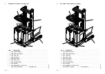
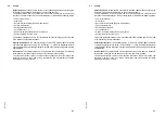
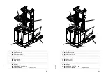
ETR safe. The operator is protected by the overhead guard (1).
The EMERGENCY STOP (9) switch can be used to quickly turn off all electrical
functions in a hazard situation. The operator display (7) indicates the following states:
– End of lift reached (
o
)
– Slow travel
– Service interval expired (Service mode active)
– Excess temperature
– Parking brake inserted
– Fork horizontal (
o
)
– Dead man switch (safety switch) is not active
– System warning / System error
Line-break protection devices in the lift cylinders limit the lowering speed of the load
if the hydraulic system malfunctions.
Display instruments:
The operator display
(7) with LCD display (
t
) or on-board
computer with large screen using TFT technology (
o
), each with integrated residual
charge display, battery discharge indicator, lift and travel profile settings and steering
angle display.
Drive motor:
The complete drive unit is screwed into the vehicle frame. A stationary
three-phase motor powers the drive wheel (6) via a spur bevel gearing.
The electronic traction current control ensures continuous drive motor speed and
therefore a smooth, even ride, strong acceleration and electronically controlled
breaking with energy recovery.
Содержание ETR 314
Страница 1: ...Operating instructions 50 452 907 ETR 314 320 u 06 06 11 09 07 08 E Manual de instrucciones...
Страница 7: ...0608 USA I 4 0608 USA I 4...
Страница 9: ...0606 USA A 2 0606 USA A 2...
Страница 24: ...D 9 0107 USA D 9 0107 USA...
Страница 26: ...D 11 0107 USA D 11 0107 USA...
Страница 103: ...0107 USA F 10 0107 USA F 10...
Страница 123: ...0708 USA G 20 0708 USA G 20...
Страница 135: ...0608 E I 4 0608 E I 4...
Страница 137: ...0606 E A 2 0606 E A 2...
Страница 152: ...D 9 0107 E D 9 0107 E...
Страница 154: ...D 11 0107 E D 11 0107 E...
Страница 162: ...E 3 0608 E 1 2 18 17 4 5 3 6 7 8 9 10 11 12 13 14 15 16 E 3 0608 E 1 2 18 17 4 5 3 6 7 8 9 10 11 12 13 14 15 16...
Страница 164: ...E 5 0608 E 1 2 18 17 4 5 3 6 7 8 9 10 11 12 13 14 15 16 E 5 0608 E 1 2 18 17 4 5 3 6 7 8 9 10 11 12 13 14 15 16...
Страница 225: ...0608 E E 66 0608 E E 66...
Страница 235: ...0107 E F 10 0107 E F 10...
Страница 255: ...0708 E G 20 0708 E G 20...


