Installation
XHD Installation, Operation, and Maintenance Manual
36
Check
Explanation/comment
Checked
If more than one pump operates from
the same liquid source, check that
separate suction-piping lines are used
for each pump.
This recommendation helps you to achieve a
higher pump performance and prevent vapor
locking especially with specific gravity of liquid
less than 0.60.
If necessary, make sure that the suc-
tion piping includes a drain valve and
that it is correctly installed.
—
Assure adequate insulation is applied
for liquids with specific gravity less than
0.60.
To assure sufficient NPSHa.
Liquid source below the pump
Check
Explanation/comment
Checked
Make sure that the suction piping is
free from air pockets.
This helps to prevent the occurrence of air and
cavitation in the pump inlet.
Check that the suction piping slopes
upwards from the liquid source to the
pump inlet.
—
If the pump is not self-priming, check
that a device for priming the pump is
installed.
Use a foot valve with a diameter that is at least
equivalent to the diameter of the suction piping.
Liquid source above the pump
Check
Explanation/comment
Checked
Check that an isolation valve is in-
stalled in the suction piping at a dis-
tance of at least two times the pipe
diameter from the suction inlet.
This permits you to close the line during pump
inspection and maintenance.
Do not use the isolation valve to throttle the pump.
Throttling can cause these problems:
• Loss of priming
• Excessive temperatures
• Damage to the pump
• Voiding the warranty
Make sure that the suction piping is
free from air pockets.
This helps to prevent the occurrence of air and
cavitation in the pump inlet.
Check that the piping is level or slopes
downward from the liquid source.
—
Make sure that no part of the suction
piping extends below the suction flange
of the pump.
—
Make sure that the suction piping is
adequately submerged below the sur-
face of the liquid source.
This prevents air from entering the pump through
a suction vortex.
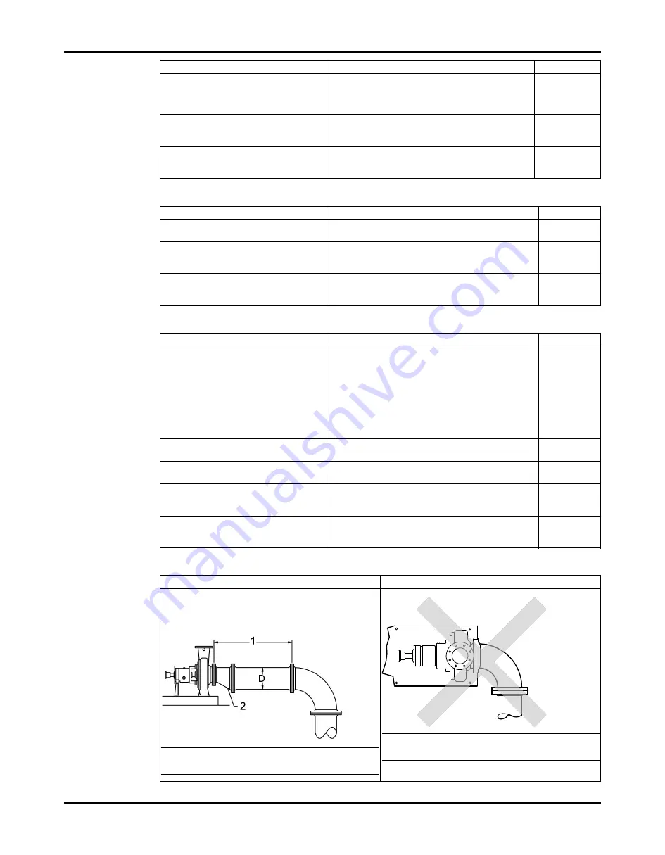
Example: Elbow (or other flow disruption) close to the pump suction inlet
Correct
Incorrect
The correct distance between the inlet flange of the
pump and the closest flow disruption (elbow, valve,
strainer, or expansion joint) must be a least five pipe
diameters.
NOTICE: This illustration shows a correctly installed
elbow.
NOTICE: This illustration shows an incorrectly in-
stalled elbow.
Содержание Goulds Pumps XHD
Страница 1: ...Installation Operation and Maintenance Manual XHD ...
Страница 2: ......
Страница 27: ...Installation XHD Installation Operation and Maintenance Manual 25 Direct coupled baseplate leveling worksheet ...
Страница 147: ...Parts Listings and Cross Sectionals XHD Installation Operation and Maintenance Manual 145 Figure 130 Optional features ...
Страница 151: ...Parts Listings and Cross Sectionals XHD Installation Operation and Maintenance Manual 149 ...
Страница 153: ...Certification CE or CE ATEX XHD Installation Operation and Maintenance Manual 151 ...
Страница 154: ...Certification CE or CE ATEX XHD Installation Operation and Maintenance Manual 152 ATEX notification ...
Страница 155: ...Certification CE or CE ATEX XHD Installation Operation and Maintenance Manual 153 IECEx Certificate of Conformity ...
Страница 156: ...Certification CE or CE ATEX XHD Installation Operation and Maintenance Manual 154 ...
Страница 157: ...Certification CE or CE ATEX XHD Installation Operation and Maintenance Manual 155 Chinese Certificate of Conformity ...


