ACSetup programme
Positioning module IMD20, IMD40
If a conversion is not wanted, the same value can be given for both the forward feed constant and the
encoder resolution; the conversion factor would be 1.
The encoder resolution must be indicated as the quadruple of the number of lines on the encoder (4-
edge evaluation).
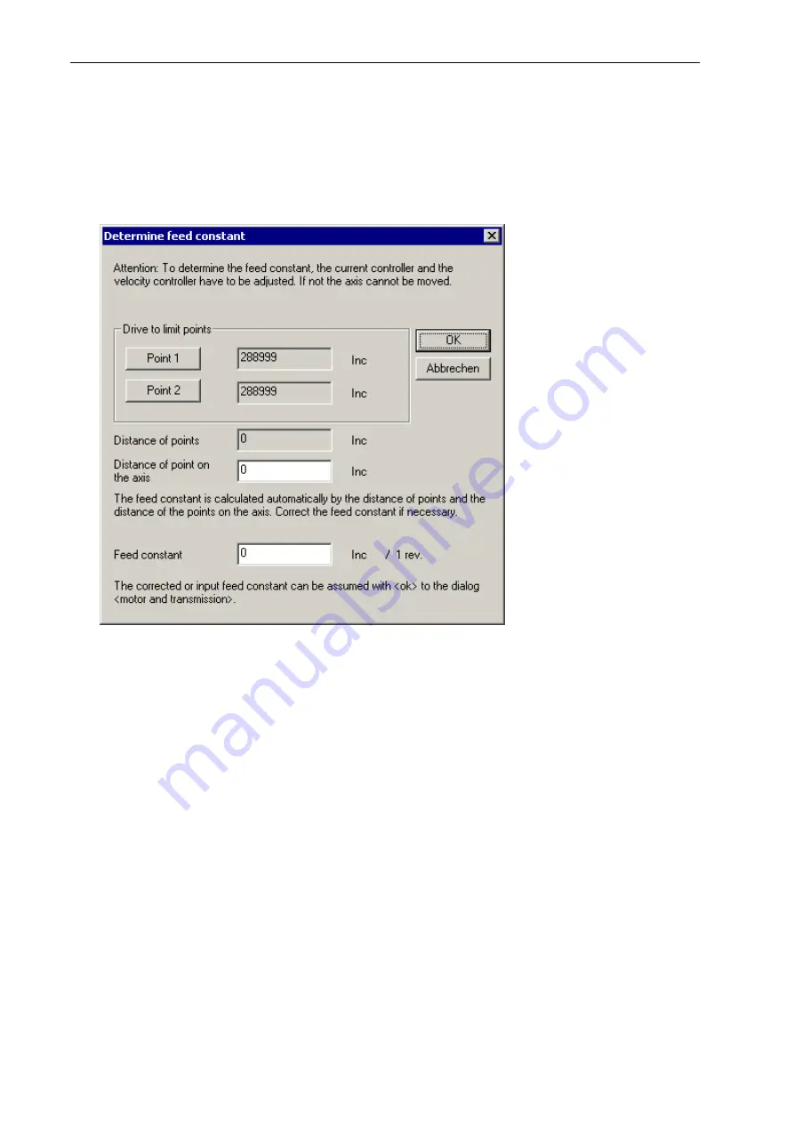
With the button „Measure Feed constant“ you can determine the feed constant out of the distance of
two points on the axis. The following dialogue appears:
With
distan
th
axis. Measure the
c
on the axis”. The
d c
distance into the edit field.
c
nt into
dia
The th
informa
six ma
informatio
e IMD20/IMD40 uses the entered encoder index position to commutate the motor precisely. At
ear drives it is often the case that the used length measuring system delivers no index signal. For
ISEL motor please press the button "Default values for ISEL motors". In the
c
nt to use a your own motor together with IMD20/IMD40 communicate with us. We will
elp you to determine the hall sensor and index signal positions.
e buttons „Point 1” and “Point 2” you can drive to two different points on the
of the two points and input the distance in the edit field “Distance of points
e
fee
Corre
onstant is calculated automatically while entering the measured
t the calculated feed constant if necessary. With “OK” you can assume the feed consta
logue box motor and transmission.
ree hall sensors according to the 3 motor phases delivers directly after switch-on the
tion in which of the six magnetic field conditions the motor is located. The raw positions of the
gnetic conditions are given by the six here entered hall sensor positions. With this raw position
n the motor can turn one revolution, until the first index signal comes. At this point of time
the
th
lin
this case the option encoder index emulation must be used to generate the index signal. For torque
motors it is recommended to use the encoder index emulation.
In the case you have a
ase you wa
h
62


