Positioning module IMD20, IMD40
Description of the drive module
is controlled via the Can bus or the serial interface, while there are only two states for the other
modes of operation (Enabled, Disabled) which are linked directly with the enabling signal (Input 4).
The active mode of operation of the drive module is defined through the settings of the DIP switch on
the front side and through the “Modes of operation” parameter ("Modes of Operation", 6060
h
).
See “Mode of operation” on page 101 .
When the module is switched on, the DIP switch is queried at first. If the node address is set to 0 at
the DIP switch the operation mode “velocity controller analogue input” is set. If the node address is
unequal 0 the parameter „modes of operation“ is evaluated.
Node address
Mode of operation
Modes of
operation
1
Profile position mode
3 Profile
velocity
mode
6
Reference run (homing mode)
7
Interpolation (interpolated position mode)
-2
Velocity control, analogue input
Node addr
Mode of op
ess unequal 0.
eration is set by
the parameter „Modes of
operation“
-3
Moving the axis away from a limit switch
Node address equal 0
Velocity control, analogue input
LED
s IMD20
1
+5V
11
+40-95V
1
STS1
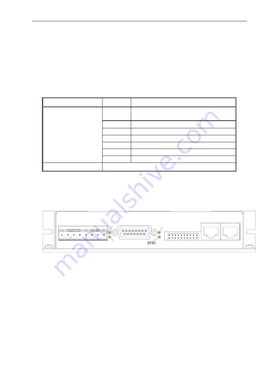
Via the LEDs on the front, it is possible to indicate the existence of the two main supply voltages.
Furthermore, the current state of the module can be viewed here (STS1 and STS2).
In case of a fault (Fault state), the two-digit error code of the current fault is given via a blinking code.
1st digit: number of blinking impulses of both status LEDs (STS1 und STS2).
2nd digit: number of blink impulses of LED STS2.
See "EMCY" on page 86 for the description of the error code.
19


