2-26
2
2.11.3 4829A Jumper Settings
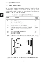
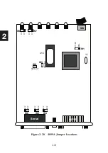
The 4829A has seven jumpers as shown in Figure 2-19. Table 2-7 lists the
4829A jumper functions and their factory settings.
TABLE 2-7 4829A JUMPER SETTINGS
Jumper
Functions
Factory
Setting
W1
Write Enable - Must be in place to write to or to save
Installed
data in the 4819A’s flash memory.
W2
Power Selection - Selects input power. P1 position selects
REG
the terminal block for a 5 Vdc regulated power source.
REG selects the regulator output for 5.5 to 15 Vdc power.
W3
Default - Install and power cycle the unit to reset the unit to Omitted
its factory default settings. Leave out for normal operation.
W4
Connects SD pair to RD signal pair. Install for half-duplex
Open*
W5
operation, omit for full-duplex operation.
W6
Enables RD transceiver 100% of time (Full-duplex) or only Full*
when transmitting (Half-duplex operation)
W7
Jumpers GPIB logic ground to chassis ground.
Omitted
Notes: * Set the RS485 setting to match your jumper setting.
J1
GPIB
J3
Internal
Serial I/O
4829A
PWR
TALK
SRQ
RDY
LSTN
ERR
P1
RE
G
W2
W1
W3
+P1-
Default
W4
W7
W5
J2
Rear Panel
Serial I/O
W6
Chassis Gnd
Full Half
Figure 2-19 4829A Jumper Locations
Содержание 4809A
Страница 5: ...ii This page left intentionally blank...
Страница 51: ...2 30 2 This page left intentionally blank...
Страница 89: ...4 8 4 This page intentionally left blank...
Страница 99: ...5 10 5 This page left intentionally blank...
Страница 125: ...A 26 A3 This page intentionally left blank...
Страница 131: ...I Index 6 This page left intentionally blank...

