


2-13
2
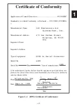
2.8
GPIB CONNECTIONS
2.8.1 4819A, 4829A and 4899A GPIB Connections
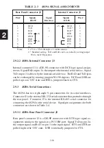
The 4819A, 4829A and 4899A have standard 24-pin IEEE-488 connector
with metric lock studs. Their IEEE-488 connector mates with all stan-
dard IEEE 488/GPIB bus cables. Signal-pin assignments for the standard
IEEE-488 connector are shown in Figure A-2 in the Appendix.
2.9
2.8.2 4809A GPIB Connections
The 4809A has two male flat-ribbon male connectors that can be used to
connect the 4809A to the GPIB bus. Connector J1 is a 24-pin connector
that is designed for pin-to-pin connection to the GPIB. Connector J2 is a
26-pin connector that contains the address switch input signals and the GPIB
bus signals. The 4809A only requires that one of the connectors be used to
connect it to the GPIB bus. The unused connector should be left open.
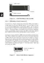
2.8.2.1 GPIB Connector J1
The GPIB Signal-pin assignments for J1 are identical to a standard IEEE-488
connector as shown in Figure A-2 in the Appendix. The J1 connector layout
is shown in Figure 2-5. Use a flat ribbon cable like ICS’s 114439-L cable
with a 24-pin plug on one end and a GPIB connector on the other end to
connect J1 to the GPIB bus. Cut an opening for the GPIB connector on
the rear panel (See cutout A and holes C in Figure 2-1). Mount the GPIB
connector on the rear panel of the chassis with the metric lockstuds. Fab-
ricate a flat ribbon cable as shown in Figure 2-6 or purchase it from ICS
Electronics as P/N 114439-L where L is the cable length in cm.
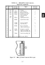
Figure 2-5
4809A J1 GPIB
Connector-Pin
Layout
24
23
22
21
20
19
18
17
16
15
14
13
12
11
10
9
8
7
6
5
4
3
2
1
PC
Board
Edge
J2
J1
Содержание 4809A
Страница 5: ...ii This page left intentionally blank...
Страница 51: ...2 30 2 This page left intentionally blank...
Страница 89: ...4 8 4 This page intentionally left blank...
Страница 99: ...5 10 5 This page left intentionally blank...
Страница 125: ...A 26 A3 This page intentionally left blank...
Страница 131: ...I Index 6 This page left intentionally blank...