2-8
2
2.6
RUNNING ICS'S CONFIGURATION PROGRAM
The configuration program supports the standard configurable items. Spe-
cial settings such as the user's IDN message will have to be entered with
a live keyboard program (such as ICS's GPIBkybd program) or as part of
the user's program (See section 3.8.6).
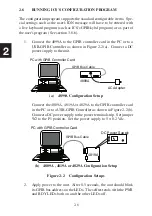
1. Connect the 4899A to the GPIB controller card in the PC or to a
USB-GPIB Controller as shown in Figure 2-2(a). Connect a DC
power supply to the unit.
GPIB Bus Cable
AC Adapter
4899A
PC with GPIB Controller Card
(a) 4899A Configuration Setup
Connect the 4809A, 4819A or 4829A to the GPIB controller card
in the PC or to a USB-GPIB Controller as shown in Figure 2-2(b).
Connect a DC power supply to the power terminal strip. Set jumper
W2 to the P1 position. Set the power supply to 5 ± 0.2 Vdc.
GPIB Bus Cable
4819A
DC Power Supply
PC with GPIB Controller Card
(b) 4809A , 4819A or 4829A Configuration Setup
Figure 2-2 Configuration Setups
2. Apply power to the unit. After 0.5 seconds, the unit should blink
its GPIB bus address on the LEDs. The selftest ends with the PWR
and RDY LEDs both on and the other LEDs off.
Содержание 4809A
Страница 5: ...ii This page left intentionally blank...
Страница 51: ...2 30 2 This page left intentionally blank...
Страница 89: ...4 8 4 This page intentionally left blank...
Страница 99: ...5 10 5 This page left intentionally blank...
Страница 125: ...A 26 A3 This page intentionally left blank...
Страница 131: ...I Index 6 This page left intentionally blank...

