3-23
3
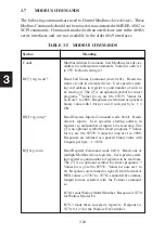
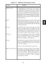
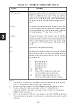
The following section provides information on how to program the 4809A,
4819A and 4899A to set its configuration and how to send commands to the
Modbus slave device. New users should try these simple examples with a
live keyboard program like ICS’s GPIBkybd program to become familiar
with controlling the GPIB<->Modbus Interface and Modbus device(s) from
the GPIB bus. Although the comments refer to a 4899A, they apply to all
units unless otherwise noted.
The Visual Basic TempCltr example program on the Support CD-ROM can
be used as an example when writing Temperature Control programs.
Modbus commands should not be mixed on the same
command line with IEEE-488.2 and SCPI commands
to prevent query errors and confusing the GPIB-to-
Modbus Interface.
3.8.1 General Configuration Guidelines
New units are factory set so that they are ready to be used when received.
Table 1-1 lists the Factory Configuration. To change the configuration, the
user should follow the sequence outlined below:
Send IFC
‘gets control, asserts REN
Send SCPI command
‘change a setting
Send SCPI query
'
verify new setting
Send *ESR?
‘query the Event Status Register to be
sure that there were no errors or
visually check the ERR LED.
Repeat the change and verify steps for each parameter you are changing.
When done save the new values.
Send “*SAV 0”
‘save the new configuration
The *SAV 0 command will cause the 4899A to blink all but one of its
LEDs. Pay close attention to the ERR LED when sending commands. If
it comes on, the unit’s parser detected a problem with the command and
DID NOT execute it.
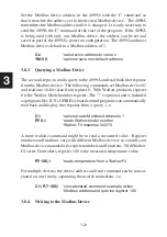
3.8.2 Setting the Modbus Device Address
Содержание 4809A
Страница 5: ...ii This page left intentionally blank...
Страница 51: ...2 30 2 This page left intentionally blank...
Страница 89: ...4 8 4 This page intentionally left blank...
Страница 99: ...5 10 5 This page left intentionally blank...
Страница 125: ...A 26 A3 This page intentionally left blank...
Страница 131: ...I Index 6 This page left intentionally blank...


