2-25
2
2.11.2 4819A Jumper Settings
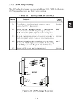
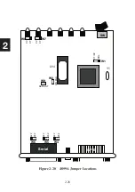
The 4819A has five jumpers as shown in Figure 2-18. Table 2-6 lists the
4819A jumper functions and their factory settings.
TABLE 2-6 4819A JUMPER SETTINGS
Jumper Functions
Factory
Setting
W1
Write Enable - Must be in place to write to or to save
Installed
data in the 4819A’s flash memory.
W2
Power Selection - Selects input power. P1 position selects
REG
the terminal block for a 5 Vdc regulated power source.
REG selects the regulator output for 5.5 to 15 Vdc power.
W3
Default - Install and power cycle the unit to reset the unit to Omitted
its factory default settings. Leave out for normal operation.
W4
TxD/RxD Signal Swapping Jumper Pair - W4 can be used
DCE
to swap the TxD/RxD pins on connector J3. Factory setting
is the DCE position with the pinouts listed in Table 2-2.
W5
Jumpers GPIB logic ground to chassis ground.
Omitted
J1
GPIB
J3
Internal
Serial I/O
4819A
PWR
TALK
SRQ
RDY
LSTN
ERR
W2
P1
RE
G
W1
J2
Rear Panel
Serial I/O
W3
+P1-
DTE
DCE
W4
W5
Chassis
Figure 2-18 4819A Jumper Locations
Содержание 4809A
Страница 5: ...ii This page left intentionally blank...
Страница 51: ...2 30 2 This page left intentionally blank...
Страница 89: ...4 8 4 This page intentionally left blank...
Страница 99: ...5 10 5 This page left intentionally blank...
Страница 125: ...A 26 A3 This page intentionally left blank...
Страница 131: ...I Index 6 This page left intentionally blank...


