background image

Chapter 14. Administration - Support 

391

Draft Document for Review March 28, 2011 12:24 pm

7914support2-0209.fm

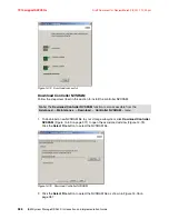
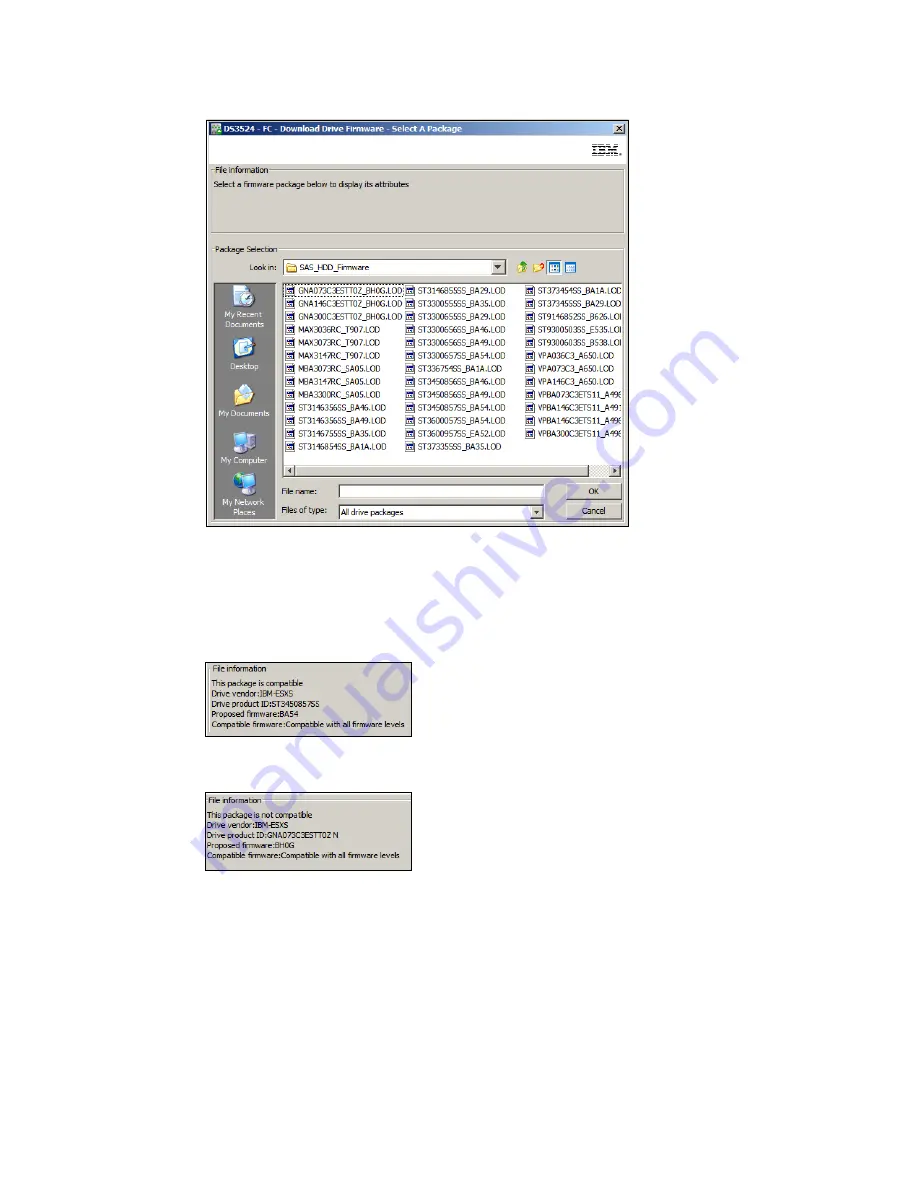
Figure 14-82   Download Drive Firmware - Select A Package

As you highlight each package listed in the Window shown in Figure 14-82, the File 
Information
 section will report if the selected drive firmware package is Compatible 
(Figure 14-83) or Not Compatible (Figure 14-84) with the types of drives that are installed in 
your system.

Figure 14-83   Drive firmware is compatible

Figure 14-84   Drive firmware is not compatible

Содержание DS3500

Страница 1: ...torage DS3500 Introduction and Implementation Guide Sangam Racherla Reza Fanaei Aghdam Hartmut Lonzer L G Len O Neill Mario Rodriguez Vaclav Sindelar Alexander Watson Sample configurations with step by step instructions Configuration and administration with Storage Manager Toubleshooting and Maintenance ...

Страница 2: ......

Страница 3: ...International Technical Support Organization IBM System Storage DS3500 Introduction and Implementation Guide September 2010 Draft Document for Review March 28 2011 12 24 pm 7914edno fm SG24 7914 00 ...

Страница 4: ...act with IBM Corp 7914edno fm Draft Document for Review March 28 2011 12 24 pm First Edition September 2010 This edition applies to IBM System Storage DS3500 running Firmware version 7 70 IBM System Storage DS Storage Manager version 10 70 This document created or updated on March 28 2011 Note Before using this information and the product it supports read the information in Notices on page xv ...

Страница 5: ...iii Draft Document for Review March 28 2011 12 24 pm 7914edno fm ...

Страница 6: ...iv IBM System Storage DS3500 Introduction and Implementation Guide 7914edno fm Draft Document for Review March 28 2011 12 24 pm ...

Страница 7: ...20 2 5 DS3500 and DS3950 Comparisons 22 2 6 IBM System Storage DS Storage Manager 23 Chapter 3 IBM System Storage DS3500 Storage System planning tasks 29 3 1 Planning your SAN and storage server 30 3 1 1 SAN zoning for the DS3500 Storage System 31 3 1 2 Zoning considerations for Enhanced Remote Mirroring 33 3 2 Planning for physical components 33 3 2 1 Rack considerations 33 3 2 2 SAS cables and c...

Страница 8: ...er host 87 Chapter 4 IBM System Storage DS3500 and EXP3500 Cabling 89 4 1 DS3500 controller connectors 90 4 1 1 DS3500 controller with standard port configuration 90 4 1 2 DS3500 controller with optional SAS host port adapter 90 4 1 3 DS3500 controller with optional Fibre Channel host port adapter 91 4 1 4 DS3500 controller with optional iSCSI host port adapter 91 4 1 5 EXP3500 ports 91 4 2 Enclos...

Страница 9: ...rage subsystems 154 5 4 2 Performing a manual discovery of storage subsystems 155 5 4 3 Add Storage Subsystem verification 158 Chapter 6 Administration Enterprise Management 161 6 1 Enterprise Management window overview 162 6 1 1 Initial Setup Tasks 162 6 1 2 Enterprise Management window 163 6 2 Functions in the Enterprise Management window 165 6 2 1 Subsystem context menu 165 6 2 2 The Enterprise...

Страница 10: ... 3 Add Free Capacity Drive 236 9 3 4 Secure Drive 237 9 3 5 Delete and Rename 237 9 3 6 Replace Drive 238 9 4 Working with Free Capacity 238 9 4 1 Create Logical Drive 239 9 5 Working with Logical Drive 244 9 5 1 Change Modification Priority 245 9 5 2 Change Cache Settings 247 9 5 3 Change Media Scan Settings 250 9 5 4 Change Pre Read Redundancy Check 252 9 5 5 Change Ownership Preferred Path 253 ...

Страница 11: ...atic configuration 310 12 6 2 Configure hot spare drives 313 12 6 3 Create arrays and logical drives 313 12 7 Map Logical Drives 314 12 8 Save Configuration 314 12 9 Manually Define Hosts 315 12 10 Configure Ethernet Management Ports 316 12 11 View Enable Premium Features 316 12 12 Manage iSCSI Settings 316 Chapter 13 Administration iSCSI 317 13 1 Planning for iSCSI attachment 318 13 2 iSCSI Confi...

Страница 12: ... 415 14 12 Troubleshooting Prepare for removal 418 14 13 Recovery Guru Recover from Failure 419 14 14 Common Recovery Commands 421 14 14 1 Initialize 422 14 14 2 Revive drive 425 14 14 3 Recovery Clear Configuration 426 14 14 4 Recovery Place controller 428 14 14 5 Recovery Reset controller 432 14 14 6 Recovery Enable controller data transfer 433 14 14 7 Recovery Place Logical drives online 434 14...

Страница 13: ...rity considerations 500 16 2 Installing and setting up RSM 502 16 2 1 Installing the host OS 503 16 2 2 Installing RSM 503 16 2 3 Setting up RSM 503 16 2 4 Configuring SNMP traps in Storage Manager 520 16 2 5 Activating RSM 522 16 2 6 Remote access security 524 16 2 7 Managing alerts 529 Chapter 17 Command Line Interface CLI 533 17 1 How to Use the Command Line Interface 535 17 1 1 Usage Notes 535...

Страница 14: ...orum configuration 589 19 4 5 Steps for configuring a two node file server cluster 595 Chapter 20 SuSE Linux configuration guide 603 20 1 DS3500 SAS storage configuration on SLES 11 using RDAC 604 20 1 1 Preparing for the installation 604 20 1 2 Installing the RDAC Multipath Driver 610 20 1 3 Setting up the DS3500 logical drives and host mapping 611 20 1 4 Scan and verify the storage logical drive...

Страница 15: ... 22 3 DS3500 Storage configuration 668 22 3 1 Mapping LUNs to a storage partition 669 22 3 2 Steps for verifying the storage configuration for VMware 669 22 4 Installing the VMware ESX Server 671 22 4 1 Configuring the hardware 671 22 4 2 Configuring the software on the VMware ESX Server host 675 22 4 3 Connecting to the VMware vSphere Server 698 22 4 4 Post Install Server configuration 706 22 4 5...

Страница 16: ...7914TOC fm Draft Document for Review March 28 2011 12 24 pm xiv IBM System Storage DS3500 Introduction and Implementation Guide ...

Страница 17: ...s will be incorporated in new editions of the publication IBM may make improvements and or changes in the product s and or the program s described in this publication at any time without notice Any references in this information to non IBM Web sites are provided for convenience only and do not in any manner serve as an endorsement of those Web sites The materials at those Web sites are not part of...

Страница 18: ...ed States other countries or both AIX 5L AIX Application Advantage BladeCenter DB2 DS4000 DS6000 DS8000 Express Storage FlashCopy GPFS IBM Netfinity Power Systems POWER6 POWER Redbooks Redbooks logo System i System p System Storage DS System Storage System x Tivoli TotalStorage The following terms are trademarks of other companies Java and all Java based trademarks are trademarks of Sun Microsyste...

Страница 19: ...lity and cost Delivering solid input output per second IOPS and throughput the DS3500 controllers offer balanced and sustainable performance The DS3500 can effectively double the performance of the previous DS3000 series of storage systems in both throughput and IOPS The DS3500 DS Storage Manager is the same management software offered with the DS5000 and DS4000 series Now any of these storage sys...

Страница 20: ...V He is an IBM Certified Systems Expert System x BladeCenter IBM Certified Specialist Midrange Storage Technical Support and VMware Certified Professional Hartmut Lonzer is a Technical Consultant in the Partnership Solution Center Southwest Germany As former Storage FTSS member his main Focus is on Storage and System x Today he is responsible to educate and support the Business Partner and Custome...

Страница 21: ... before he came to IBM He holds a Master s degree in computer science from the Technical University of Brno in the Czech Republic Alexander Al Watson is an ATS Specialist for Storage Advanced Technical Skills ATS Americas in the United States He is a Subject Matter Expert on SAN switches and the IBM Midrange system storage products He has over fifteen years of experience in planning managing desig...

Страница 22: ...chnical contacts and relationships Residencies run from two to six weeks in length and you can participate either in person or as a remote resident working from your home base Find out more about the residency program browse the residency index and apply online at ibm com redbooks residencies html Comments welcome Your comments are important to us We want our books to be as helpful as possible Sen...

Страница 23: ...s on LinkedIn http www linkedin com groups home gid 2130806 Explore new Redbooks publications residencies and workshops with the IBM Redbooks weekly newsletter https www redbooks ibm com Redbooks nsf subscribe OpenForm Stay current on recent Redbooks publications with RSS Feeds http www redbooks ibm com rss html ...

Страница 24: ...7914pref fm Draft Document for Review March 28 2011 12 24 pm xxii IBM System Storage DS3500 Introduction and Implementation Guide ...

Страница 25: ...ontext of the IBM System Storage DS3500 We discuss the following technologies Fibre Channel FC Serial Attached SCSI SAS Internet SCSI iSCSI Fibre Channel has traditionally been used to attach storage subsystems in midrange and large scale environments However as the DS3500 products are geared towards Small and Medium Business SMB and departmental environments SAS and iSCSI attachment technologies ...

Страница 26: ...oint Two devices are connected directly to each other This is the simplest topology and provides a direct link between an FC HBA inside a host server and a storage device with limited connectivity Arbitrated loop This topology can be used to interconnect several FC devices A typical example would be to attach a certain number of host servers to an FC storage subsystem A loop can consist of up to 1...

Страница 27: ...he 8b 10b encoding and decoding of signals for transmission across the physical media FC2 is the network layer and defines the main FC protocols This layer defines how the frames are transferred FC3 is the common services layer This layer provides services such as multi casting and striping FC4 is the application protocol mapping layer In storage connectivity applications FCP protocol is used to e...

Страница 28: ...wever in situations where very long cable lengths are needed single mode cabling will be required Despite its name Fibre Channel signaling can run on both copper wire and fiber optic cables as shown in Figure 1 2 Figure 1 2 FC Cable Types Small form factor pluggable SFP transceiver The small form factor pluggable SFP or Mini GBIC is a compact hot pluggable transceiver used for both telecommunicati...

Страница 29: ...N defined by the IEEE Original format addresses are assigned to manufacturers by the IEEE standards committee and are built into the device at build time similar to an Ethernet MAC address First 2 bytes are either hex 10 00 or 2x xx where the x s are vendor specified followed by the 3 byte vendor identifier and 3 bytes for a vendor specified serial number New addressing schema first nibble is eith...

Страница 30: ...g In the current DS3500 implementation up to 96 drives can be configured in a single DS3500 using three EXP3500 expansion units SAS protocol layers The SAS protocol consists of four layers The physical or phy layer This layer represents the hardware components such as transceivers which send and receive electrical signals on the wire The link layer The link layer manages connections across phy int...

Страница 31: ... the link one is still busy then link two will manage the overflow of data that cannot be transmitted by link one If link one finishes its transmission of data then the next block of data will be transmitted on link one again otherwise another link will be used In this way for heavy I O workloads it is possible that all links are being used at certain times providing a simultaneous data speed of 2...

Страница 32: ...oyment can be severely degraded if not operated on a dedicated network or subnet LAN or VLAN As a result iSCSI is often seen as a low cost alternative to Fibre Channel which requires dedicated infrastructure except in its Fibre Channel over Ethernet FCoE form IP SANs are a cheaper alternative to FC SANs however the lower cost of iSCSI also implies lower performance and scalability Encapsulation ha...

Страница 33: ...n a kernel resident device driver that uses the existing network card NIC and network stack to emulate SCSI devices by speaking the iSCSI protocol Software initiators are available for most operating systems and this type is the most common mode of deploying iSCSI An example of an iSCSI stack is the Microsoft iSCSI Software Initiator which runs on Windows Server 2003 Windows Server 2008 and VMware...

Страница 34: ...processing of the iSCSI protocol layer itself but the CPU overhead for that task is low iSCSI HBAs or TOEs are used when the additional performance enhancement justifies the additional expense of using an HBA for iSCSI rather than using a software based iSCSI client initiator An iSCSI target usually represents hard disk storage that works over the IP or Ethernet networks DS3500 Other types of peri...

Страница 35: ...An administrator can statically define the iSCSI targets to the host system initiator This process allows the administrator to specify the iSCSI target node name and IP address port to the host system initiator or its host bus adapter HBA iSCSI HBAs should support an administrator defining this information This type of discovery is useful in small installations and is known as static discovery Que...

Страница 36: ...ge Handshake Authentication Protocol CHAP which includes a mechanism to prevent cleartext passwords from appearing on the wire When enabled the iSCSI target will authenticate the initiator Optionally the initiator can authenticate the target as well Each connection within a session has to be authenticated In addition to CHAP several authentication methods can be used Secure Remote Password SRP Ker...

Страница 37: ... new IBM System Storage DS3500 Storage Subsystem offerings and functionality These products consists of different models of storage subsystems which provide for a variety of different environments to meet various user needs We describe the EXP3512 and EXP3524 SAS disk drive enclosures as well We also explain the Premium Features philosophy and how the Storage Manager utility works with these new p...

Страница 38: ...management being shared by all The overall positioning of these new DS3000 series products within the IBM System Storage DS family is shown in Figure 2 1 Figure 2 1 IBM System Storage family 2 2 DS3500 product models The new IBM System Storage DS3500 series storage subsystems support up to two redundant RAID controllers in either a twelve or twenty four drive configuration The models for the stora...

Страница 39: ...XP3524 servers assembly from the front view 2 2 1 DS3512 and DS3524 Components The DS3500 storage server is a 2U rack mountable enclosure containing either one or two RAID controller modules two power supplies and up to twelve or twenty four disks modules See Figure 2 4 for the component layouts Figure 2 4 DS 3500 components RAID controller RAID controllers support RAID levels 0 1 3 5 6 and 10 Eac...

Страница 40: ... DS3500 power supply module is a 585 Watt DC power supply It is auto ranging 100 240VAC input capable As shown in Figure 2 5 the power supply provides LED indicators for the following states starting from left Standby power LED green Currently this LED is not used DC power LED green When this LED is lit it indicates that the DS3500 is turned on and is supplying both 5 volt and 12 volt dc power OK ...

Страница 41: ...n the cabling and use of with the bladecenter and standalone environments see 4 8 Host attachment on page 110 Figure 2 7 Controller module with optional SAS host interface daughter card Figure 2 8 shows the iSCSI optional daughter card installed in the controller With this option the subsystem will have up to eight iSCSI connections for host attachments For details on the cabling and use of with t...

Страница 42: ...12 and EXP3524 expansion subsystems allow for the growth of the DS3500 storage subsystem up to the 96 drive maximum by adding either the twelve or twenty four drive chassis to the storage server s SAS drive expansion port Any mix of the expansion models can be added up to the maximum allowed drive count The EXP3512 and EXP3524 differ from the DS3512 and DS3524 in that in place of the controller mo...

Страница 43: ...XP3524 rear view with SAS port connections With the EXP 3512 and EXP3524 only one of the two IN ports are used on each ESM to connect expansions together into a cascaded loop configuration As shown in Figure 2 11 on page 20 the cabling scheme used for connecting these expansions follows what is known as a top down bottom up method This provides the expansion loops with redundant paths to the enclo...

Страница 44: ...00 with Windows and Linux on Intel host attach license this can be increased to 8 16 32 or 64 The maximum number of storage partitions is 64 on all DS3500 products Use the DS3500 Partition Expansion License to enable all 64 storage partitions DS3000 FlashCopy Expansion License This feature enables FlashCopy FlashCopy is a point in time copy of a source logical drive The FlashCopy logical drive bec...

Страница 45: ...s a prerequisite for VolumeCopy DS3000 FlashCopy VolumeCopy License As stated above the FlashCopy Premium Feature must be enabled before you can enable and use VolumeCopy For this reason IBM provides the FlashCopy VolumeCopy license this is actually a bundle of both Premium Features DS3000 Enhanced Remote Mirroring ERM With the DS3500 and DS3950 ERM provides a way to create a remote image copy of ...

Страница 46: ...parison Table 2 2 DS3500 and DS3950 Specification comparisons Fully configured systems DS3500 DS3950 Host interfaces Eight 8 Gb s FC and four 6 Gb s SAS Eight 1 Gb s iSCSI and four 6 Gb s SAS Four or eight 6 Gb s SAS Four 8 Gbps FC or Four 8 Gbps FC and four 1 Gbps iSCSI Redundant drive channels Two 6 Gb s SAS Four 4 Gb s FC Drive enclosures 12 drive 3 5 in 2U 24 drive 2 5 in 2U 16 drive 3 5 in 3U...

Страница 47: ...anagement station is the system that is responsible for managing all or a portion of a storage network The IBM System Storage DS Storage Manager provides a GUI which runs on the management station This management station can be based on Windows Linux AIX or Solaris operating systems There may be slight screen shading differences between the different operating system version of the displays but th...

Страница 48: ...cess logical drive to manage the DS3500 controllers This means that you cannot configure the maximum number of logical drives because one of them is reserved for the access logical drive But this is usually not a problem because virtually all customers will find the maximum number of logical drives more than sufficient An example of in band management is shown in Figure 2 12 Two host servers are a...

Страница 49: ...he access logical drive is that target device The access logical drive is also sometimes referred to as the Universal Transport Mechanism UTM device or the Universal XPort device Out of band management Out of band management requires that the management IP addresses are configured on both controllers and that the controllers management ports are connected to the management network This should be a...

Страница 50: ...em even in the case of I O path or Ethernet management network failure The IIBM System Storage DS Storage Manager package consists of the following components Storage Manager Client SMclient SMcli Storage Manager Agent SMagent Storage Manager Utility SMutil Storage Manager multipath support Java access bridge for Windows only Storage Manager Client SMclient This is the actual graphical user interf...

Страница 51: ...ministrator However it is also possible to install SMclient on a host server SMclient is available for Windows and Linux operating systems SMcli command line interface Besides providing a GUI for the management tasks SMclient also includes a component called SMcli SMcli provides a powerful command line interface CLI All the tasks available in the Storage Manager GUI can also be run using the CLI I...

Страница 52: ...t deal of detail on the current configuration settings and their impacts Multipath driver support We recommend installing two HBAs in the host servers and using the dual controller DS3500 subsystems This provides the ability to create completely redundant paths to the host server s storage therefore improving the availability through multiple I O paths to the controllers and full storage redundanc...

Страница 53: ...at are my SAN requirements What hardware do I need to buy What reliability do I require What redundancy do I need For example do I need off site mirroring What compatibility issues do I need to address Will I use any storage virtualization product such as IBM SAN Volume controller Will I use any unified storage product such as the IBM System Storage N series What operating system am I going to use...

Страница 54: ...ts The statement must have easily defined bullet points covering the requirements for example New installation or upgrade of existing infrastructure Infrastructure type s to be used SAS iSCSI fiber channel direct or fabric Host Bus Adapter HBA selection HBA driver type selection SCSIPort or StorPort Multipath Driver selection RDAC DMMP MPIO or SDDPCM Types of applications accessing the SAN whether...

Страница 55: ...soft Exchange servers These have random writes and fewer reads Typical examples of high throughput applications are data mining imaging and backup storage pools These have large sequential reads and writes By understanding your data and applications you can also better understand growth patterns Being able to estimate an expected growth is vital for the capacity planning of your DS3500 Storage Sys...

Страница 56: ...ic This helps to provide faster recovery for path failures that can be resolved through the use of an alternate connection to the same controller verses requiring the full failover process be ran The DS3500 models only support drivers that by design follow the rules for this type of path management See Figure 3 1 for an example of how the configuration should be implemented Figure 3 1 Host HBA to ...

Страница 57: ... first zone contains the ERM source DS3500 controller A and ERM target DS3500 controller A The second zone contains the ERM source DS3500 controller B and ERM target DS3500 controller B ERM is detailed further in IBM Midrange System Storage Copy Services Guide SG24 7822 3 2 Planning for physical components In this section we review elements related to physical characteristics of an installation su...

Страница 58: ...r racks and additional hardware that will require installation Store all spare materials that can burn in properly designed and protected areas Rack layout To be sure that you have enough space for the racks create a floor plan before installing the racks You might need to prepare and analyze several layouts before choosing the final plan If you are installing the racks in two or more stages prepa...

Страница 59: ...irements 3 2 2 SAS cables and connectors All DS3500 storage subsystems regardless of the optional host attachment feature added will have SAS host connections available Also with the addition of any expansion subsystems they use SAS cabling to attach expansion enclosures Therefore let us have a look at the SAS cables and connectors used The SAS ports on the DS3500 controller and EXP3500 ESM all su...

Страница 60: ...mini SAS connector into a mini SAS port Make sure that it locks into place To remove a mini SAS cable complete the following steps 1 Put one finger into the hole on the blue plastic tab on the mini SAS connector and gently pull on the tab to release the locking mechanism 2 As you pull on the tab pull out the connector to remove it from the port In Figure 3 4 on page 37 we show an example of SAS co...

Страница 61: ... public LAN for DS3500 out of band management Instead set up a dedicated LAN or VLAN just for management purposes This will provide increased security of your DS3500 storage system If the DS3500 RAID controllers are on a public LAN a knowledgeable user could install the DS3500 Storage Manager on a separate workstation or use the CLI to run potentially destructive tasks For an additional layer of s...

Страница 62: ...finally get to the other end multi mode means multiple paths for the light The light taking these various paths gets to the other end of the cable at slightly separate times separate paths separate distances and separate times The receiver has to determine which incoming signals go together The maximum distance is limited by how blurry the original signal has become The thinner the glass the less ...

Страница 63: ...ns excessive numbers of patch panels and so on can cause these maximums to be far shorter All IBM fiber feature codes that are orderable with the DS3500 Storage System will meet the standards Interfaces connectors and adapters In Fibre Channel technology frames are moved from source to destination using gigabit transport which is a requirement to achieve fast transfer rates To communicate with gig...

Страница 64: ...he same amount of space All DS3500 series products use SFP transceivers and LC fiber cables See Figure 3 7 Figure 3 7 LC fiber cable connector Interoperability of 2 Gbps 4 Gbps and 8 Gbps devices The Fibre Channel standard specifies a procedure for speedy auto detection Therefore if a 4 Gbps port on a switch or device is connected to a 2 Gbps port it must negotiate down and the link will run at 2 ...

Страница 65: ...e several switches and directors that operate at this speed FC host attachment methods With FC SAN environments there are two methods of host attachment to the storage system that are commonly used direct attached and switch attached fabric Direct attached DS3500 Figure 3 8 shows a simple direct attached configuration Two host servers are connected to a dual controller DS3500 Each server uses two ...

Страница 66: ...igured to used these ports ERM can only be used with a SAN switch environment Cable management and labeling Cable management and labeling for solutions should cover both the installation routing and labeling of all cables including power ethernet LAN network SAS for both host attachments and backend expansions and fiber channel Cable management and labeling needs have expanded from the traditional...

Страница 67: ...iber optic cables for guidance on minimum radius handling and care of fiber optic cables Run the cables neatly along the rack rear corner posts Use cable ties to secure the cables to the corner posts Make sure the cables cannot be pinched or cut by the rack rear door Run internal cables that connect devices in adjoining racks through the open rack sides Run external cables through the open rack bo...

Страница 68: ...ocation information must be broad to specific for example the site building to a specific port on a server or hub Other cabling mistakes Avoid making these common mistakes in cabling Leaving cables hanging from connections with no support Not using dust caps Not keeping connectors clean Certain cable manufacturers require the use of lint free alcohol wipes in order to maintain the cable warranty L...

Страница 69: ... Windows 2003 and 2008 and Linux support up to four paths to the storage controller AIX with MPIO can support more than four paths to the controller modules however too many paths can delay failover when it actually is needed due to a controller failure Care should be taken to ensure that there are enough redundant paths without having too many In general having four paths provides good level of r...

Страница 70: ...torage there are values at the controller as well as drive level These values can varied between code levels and performance enhancement features For the latest firmware for the DS3500 controller see the following Web site http www ibm com systems storage disk 3 2 6 Disk expansion enclosures The DS3500 Storage Systems offer the EXP3500 expansion enclosures for expanding the subsystem beyond the in...

Страница 71: ...s the need is generally for higher capacity drives and more bandwidth With the new larger drives spindle count does not need to be high to meet this goal For this environment the EXP3512 can provide the disk capacity at a lower price point Careful planning can allow for the mixing of these two expansions in the storage system to meet a mixed environment need The EXP3512 and EXP3524 enclosures supp...

Страница 72: ... to assign these manually Failure to adhere to these guidelines can cause issues with I O error recovery and make the troubleshooting of certain drive communication issues more difficult Whenever possible maintain an even number of expansion units on the DS3500 Storage System and configure it for enclosure loss protection Add EXP expansion units in pairs and ideally for the DS3500 Storage System i...

Страница 73: ...the seek time the quicker data can be read from or written to the drive The average seek time reduces when the speed of the drive increases Typically a 7 2K drive will have an average seek time of around 9 ms a 10K drive will have an average seek time of around 5 5 ms and a 15K drive will have an average seek time of around 3 5 ms Command queuing or queue depth allows for multiple commands to be o...

Страница 74: ...ise among capacity performance and data redundancy The attributes of each of these RAID levels is described in more detail over the following pages of this book Note that the maximum number of physical drives in a RAID 0 1 or 10 array is limited by the maximum number of physical drives that can be installed in a fully populated DS3500 storage subsystem which is 96 drives The maximum number of phys...

Страница 75: ... available and accessible from the second drive of the mirrored pair For each pair of mirrored drives read operations can be performed from either physical disk of the mirrored pair Write operations are performed by writing to both physical disks of the mirrored pair In this manner small blocksize writes can be completed very quickly making this RAID type a great solution for a high write intensiv...

Страница 76: ...d through the use of a write cache Always ensure that you use battery backed write cache The performance of RAID 10 is comparable to RAID 0 for sequential I Os but RAID 10 provides data redundancy through disk mirroring When comparing RAID Level 10 with RAID Level 5 RAID 10 uses two write IOs to write a single block of data one write IO to each drive in the mirrored pair RAID 5 requires two read I...

Страница 77: ...place The DS3500 storage subsystem supports a maximum of 30 drives in a RAID 3 array RAID 5 Data striping with distributed parity Like RAID Level 3 RAID Level 5 also uses parity for data protection but unlike RAID 3 it does not use a dedicated parity drive Instead the parity blocks are evenly distributed across all physical disk drives in the array as shown in Figure 3 16 The failure of a single p...

Страница 78: ...e number of write I Os for a RAID 1 and will always be twice the value of A Columns B C D E contain the numbers of read data parity and write data parity I Os required for the number of drives that are being written to You can see that for seven drives no read I Os are required for RAID 5 arrays because the full stripe is being written at once This substantially reduces the total number of I Os co...

Страница 79: ...k of data P Q that is striped across the disks The DS3500 storage subsystem performs the P Q parity calculations in hardware There is no performance penalty for read operations from a RAID 6 array but there is a performance penalty for write operations because two sets of parity information P Q must be calculated for each write operation The write penalty in RAID Level 6 may be mitigated by using ...

Страница 80: ...ood for large data transfers in applications such as multimedia or medical imaging that write and read large sequential chunks of data RAID 5 is good for multi user environments such as database or file system storage where the typical I O size is small and there is a high proportion of read activity RAID 6 offers high availability with performance slightly lower than RAID 5 RAID Description Appli...

Страница 81: ...more often than RAID 10 Exactly how often is subject to many variables and is beyond the scope of this book The money saved by economizing on drives can be easily overwhelmed by the business cost of a crucial application going down until it can be restored from backup No data protection method is 100 reliable and even if RAID were faultless it will not protect your data from accidental corruption ...

Страница 82: ...work well it is best that smaller arrays be used to better balance the drive usage and access patterns across the controllers and to avoid contention and intermixed IO patterns Configuring multiple LUNs striped across a single large array can be used to make use of all the capacity However with this layout consideration should be given to the workload types for which these LUNs will be used so as ...

Страница 83: ... alternative consists of two 8 1 parity defined to the two controllers using separate paths doing two separate streams of heavy throughput in parallel and filling all the channels and resources at the same time which keeps the whole server busy with a cost of one additional drive Further improvements can be gained by splitting the two 8 1 parity into four 4 1 parity arrays giving four streams but ...

Страница 84: ...automatically be used as a replacement drive Data reconstruction onto the hot spare will take place immediately When reconstruction finishes the array will again be in a fully operational status and the hot spare will become a member of the array Depending on your configuration it might be wise to use more than just one hot spare In small DS3500 configurations with a relatively low number of disk ...

Страница 85: ...s Explicit assignment The hot spare drives are manually selected and assigned Use the IBM DS Storage Manager to configure the above options 3 3 5 Enclosure loss protection planning Enclosure loss protection will enable your system to be more resilient against hardware failures Enclosure loss protection means that you spread your protection arrays across multiple enclosures rather than in one enclo...

Страница 86: ...ion and Implementation Guide Figure 3 20 Example of enclosure loss protection In the example shown in Figure 3 21 if enclosure number 1 fails the entire array becomes inaccessible Figure 3 21 An array without enclosure loss protection Best practice When possible plan to use enclosure loss protection for your arrays ...

Страница 87: ...use of host based volume management software products In addition typically the load across controllers and logical drives is constantly changing The logical drives and data accessed at any given time depend on which applications and users are active during that time period hence the importance of monitoring the system Enhanced remote mirror ERM considerations A secondary logical drive in a remote...

Страница 88: ...stems such as Windows will write their signatures to any device it can access Heterogeneous host support means that the host systems can run various operating systems But be aware that all host systems within a particular storage partition have unlimited access to all logical drives assigned to the partition Therefore file systems or disk structure on these logical drives must be compatible with h...

Страница 89: ... number of different heterogeneous hosts allowing for greater flexibility and scalability Note that on DS3500 models the number of partitions also depends on the premium feature licence that has been purchased For the maximum number of logical drives per partitions for a specific host type see Table 3 4 Table 3 4 Host logical drive restrictions Every mapping of a logical drive to a new host or hos...

Страница 90: ...ng create a table of planned partitions and groups so that you can clearly map out and define your environment Table 3 5 shows an example of a storage partitioning plan which clearly shows the host groups hosts port names WWN of the ports and the operating systems used in that environment Other columns can be added to the table for future references such as HBA BIOS levels driver revisions and swi...

Страница 91: ...for a single small host I O For certain storage subsystems having the segment size equal to the host I O size is preferred which is not the case with the Midrange Storage Subsystems In many cases using the segment size that is equal to the host IO size can result in multiple disk operations due to alignment differences This can be easily remedied with a larger segment size selection for small IO b...

Страница 92: ...uires that very few host I Os not equal a full stripe width 3 3 9 Media scan Media scan is a background process that checks the physical disks for defects by reading the raw data from the disk and writing it back which detects possible problems caused by bad sectors of the physical disks before they disrupt normal data reads or writes This process is sometimes known as data scrubbing Media scan co...

Страница 93: ...e RAM on the controller that has a faster access time than the drive media This cache memory is shared for read and write operations Efficient use of the RAID controller cache is essential for good performance of the DS3500 See 9 5 2 Change Cache Settings on page 247 for detailed explanation about the cache parameter settings Cache blocksize selection On the DS3500 the cache blocksize is a variabl...

Страница 94: ...ced out and written to disks This value by default is set to ten seconds but can be changed by using the Storage Manager SM command line interface command set logical Drive LUN cacheflushModifier new_value 3 4 Planning for premium features The premium features that come with the DS3500 Storage Manager software are enabled by purchasing a premium feature license key for each feature When planning f...

Страница 95: ...se logical drive remains online and user accessible The DS3500 can have up to eight FlashCopy volumes Plan carefully with regard to the space available to make a FlashCopy of a logical drive even though FlashCopy takes only a small amount of space compared to the base image 3 4 2 VolumeCopy The VolumeCopy feature is a firmware based mechanism for replicating logical drive data within a storage sub...

Страница 96: ...degradation of application response time Separating data centers by longer distances helps provide protection from regional outages This asynchronous technique can help achieve better performance for unlimited distances by allowing the secondary site to trail in data currency a few seconds behind the primary site With Global Mirror currency can be configured to be as little as three to five second...

Страница 97: ...ul authentication with the DS3500 system The Encryption Key is generated by the drive and never leaves the drive so it always stays secure It is stored in encrypted form performing symmetric encryption and decryption of data at full disk speed with no impact on disk performance Each FDE drive uses its own unique encryption key which is generated when the disk is manufactured and regenerated when r...

Страница 98: ... be used to manage the distribution of data on physical disk devices The Logical Volume Manager controls disk resources by mapping data between a simple and flexible logical view of storage space and the actual physical disks The Logical Volume Manager does this by using a layer of device driver code that runs above the traditional physical device drivers This logical view of the disk storage is p...

Страница 99: ... into physical partitions PPs of a fixed size for that physical volume Within each volume group one or more logical volumes LVs are defined Logical volumes are groups of information located on physical volumes Data on logical volumes appear contiguous to the user but can be spread striped on multiple physical volumes Each logical volume consists of one or more logical partitions LPs Each logical p...

Страница 100: ...des a number of facilities or policies for managing both the performance and availability characteristics of logical volumes The policies that have the greatest impact on performance in general disk environment are the intra disk allocation inter disk allocation write scheduling and write verify policies Best practice When using a DS3500 Storage System with operating systems that have a built in L...

Страница 101: ... example Today the Microsoft Windows operating system does not have a powerful LVM such as certain UNIX systems Distributing the traffic among controllers in such an environment might be a little bit harder Actually Windows systems have an integrated reduced version of Veritas Volume Manager also known as Veritas Foundation Suite called Logical Disk Manager LDM but it does not offer the same flexi...

Страница 102: ...pecific portion of a dynamic disk which is mapped to a specific region of a physical disk A sub disk is a portion of a dynamic disk s public region A sub disk is the smallest unit of storage in Volume Manager Therefore sub disks are the building blocks for Volume Manager arrays A sub disk can be compared to a physical partition With disk groups you can organize disks into logical collections Assig...

Страница 103: ...f managed disks from attached back end disk storage systems These managed disks are then mapped to a set of virtual disks for use by various host systems In conjunction with the DS3500 Storage System family the SAN Volume Controller SVC can increase the storage copy services functionality and also the flexibility of SAN based storage The SVC is very flexible in its use It can manage all host stora...

Страница 104: ... SLES 10 SP3 Novell SUSE SLES 11 VMware ESX 4 0 IBM AIX V6 1 TL5 HP UX 11iv2 11 23 and HP UX 11iv3 11 31 3 6 3 Clustering support The following clustering services are supported Microsoft Cluster Services HP Service Guard manager 11 18 00 3 6 4 Multipathing IBM offers various multipath drivers that you can use with your DS3500 Storage System Only one of these drivers is required Each driver offers...

Страница 105: ...ices It contains a core set of binary drivers which are installed with the DS3500 Device Specific Module DSM to provide a transparent system architecture that relies on Microsoft Plug and Play to provide LUN multipath functionality as well as maintaining compatibility with existing Microsoft Windows device driver stacks Windows 2003 2008 RHEL SLES AIX 5L V5 3 AIX V6 1 HP UX 11 23 HP UX 11 31 DS350...

Страница 106: ...Multiple Path I O MPIO a device can be individually detected through one or more physical connections or paths A path control module PCM provides the path management functions An MPIO capable device driver can control more than one type of target device A PCM can support one or more specific devices Therefore one device driver can be interfaced to multiple PCMs that control the I O across the path...

Страница 107: ... In this section we discuss the Linux multipath options Redundant Disk Array Controller The Redundant Disk Array Controller RDAC also known as Multi Path Proxy MPP is the preferred multipathing driver for Linux based operating systems such as Red Hat Enterprise Linux RHEL or SUSE Linux Enterprise Server SLES The current RDAC driver implementation performs the following tasks Detects and claims the...

Страница 108: ...to for the driver to function OS version SLES11 0 with the following patch installed patch installed lsi scsi_dh_rdac kmp default 01 00_2 6 27 19_5 1 kernel upgraded to 2 6 31 5 0 16 default DMM version device mapper 1 02 27 8 6 For detailed instructions on how to implement and use DMM with SLES 11 see Chapter 20 SuSE Linux configuration guide on page 603 3 6 10 Function of Auto Logical Drive Tran...

Страница 109: ... Figure 3 27 ADT disabled mode path failover Note In ADT disabled mode you are required to issue a redistribution command manually to get the LUNs balanced across the controllers Host Server 1 0 1 2 3 1 2 3 A 2 B 3 Failover Driver X Application 0 0 Host Server 1 0 1 2 3 1 2 3 A 2 B 3 Failover Driver X Application 0 0 Host Server 1 0 1 2 3 1 2 3 A 2 B 3 Failover Driver X Application 0 0 Host Server...

Страница 110: ...ADT enabled mode path failover 3 7 Operating system restrictions In your planning you must also consider the restrictions of your operating system that might apply We have covered the maximum file system size ordered by the operating system and their commonly used file systems the maximum number of LUNs that can be assigned to one host and the maximum logical volume size supported by various opera...

Страница 111: ...ort will soon follow You can find more information about storage partitioning in 3 3 7 Storage partitioning on page 63 Table 3 8 lists the operating system limit as well as the limit of the DS3500 Storage System Table 3 8 Maximum number of LUNs per host Operating System File system Size Linux ext2 32 TB ext3 32 TB AIX JFS2 64 PB Windows NTFS 16 EB FAT32 8 TB HP UX 11i v2 HFS 128 GB JFS 3 5 2 TB 32...

Страница 112: ...7914DS3KPlanning_090710 fm Draft Document for Review March 28 2011 12 24 pm 88 IBM System Storage DS3500 Introduction and Implementation Guide ...

Страница 113: ...P3500 enclosure and then describe the best practise guidelines for SAS expansion connections Host side connections SAS iSCSI and Fibre Channel Ethernet management connections Power cabling We also describe best practises for cable management and describe the correct power on off procedures for the IBM System Storage DS3500 For more information on all the topics discussed in this chapter you can re...

Страница 114: ... optional host adapter cards would be located You can install one of three different types of optional host adapter cards if you need additional SAS host port support or concurrent host connectivity with either SAS and FC or SAS and iSCSI The port on the extreme right is a x4 multilane mini SAS port for connecting to EXP3500 drive expansion enclosures Below SAS ports 1 and 2 there is a 7 segment n...

Страница 115: ...r Each of these ports supports a small form factor pluggable SFP transceiver and is capable of operating at 8 Gbps 4 Gbps or 2 Gbps 4 1 4 DS3500 controller with optional iSCSI host port adapter Figure 4 4 shows the rear panel of a DS3500 controller with the optional four port iSCSI host adapter installed Figure 4 4 The rear panel of a D3500 controller with the optional iSCSI host port adapter inst...

Страница 116: ...que two digit identifier for each DS3500 and EXP3500 enclosure in the storage subsystem configuration In a dual controller DS3400 subsystem both controllers should have the same enclosure ID Similarly on an EXP3000 with two ESMs both ESMs must have the same enclosure ID under normal operating conditions The default enclosure ID of the DS3500 controller is 85 and best practise is to leave this valu...

Страница 117: ...ave conflicting hardware addresses 4 3 SAS cables In this section we describe the SAS Cables that you can use to connect the DS3500 to hosts and to EXP3500 expansion enclosures Each DS3500 RAID controller has up to four x4 multilane SAS host ports and a single x4 multilane SAS port for drive channel connections IBM provides SAS cables in both 1 metre and 3 metre cable lengths for connecting to EXP...

Страница 118: ...ut excess weight on the cable at the connection point Make sure that the cable is well supported To connect a mini SAS cable insert the mini SAS connector into a mini SAS port as shown in Figure 4 8 Make sure that it locks into place Figure 4 8 Connecting a mini SAS cable Follow these steps to remove a mini SAS cable as shown in Figure 4 9 1 Put one finger into the hole on the blue plastic tab on ...

Страница 119: ...s a laser product and its function is to convert electrical signals to and from optical signals for transmission to and from the controllers You then connect the fibre optic cable to the SFP module SFP modules are available in both long wave and short wave types but only short wave SFP modules are supported in the DS3500 storage subsystem You can use the DS Storage Manager Client to view the Stora...

Страница 120: ...equires SFP modules SFP modules convert electrical signals to optical signals that are required for Fibre Channel transmission to and from RAID controllers After you install the SFP modules you use fiber optic cables to connect the storage subsystem to other Fibre Channel devices To install an SFP module complete the following steps 1 Remove the SFP module from its static protective package 2 Remo...

Страница 121: ...le from the host port complete the following steps 1 Remove the LC LC Fibre Channel cable from the SFP module 2 Unlock the SFP module latch For SFP modules that contain plastic tabs unlock the SFP module latch by pulling the plastic tab outward 10 as shown in Figure 4 13 Figure 4 13 Unlocking the SFP module latch plastic variety For SFP modules that contain wire tabs unlock the SFP module latch by...

Страница 122: ...n use for connecting to the small form factor pluggable SFP modules in the DS3500 storage subsystem We also describe best practises for cable management of fibre optical cables Because the DS3500 only supports SFP modules Fibre Channel cables with LC connectors are required Connectors that plug into SFF or SFP devices are called LC connectors The two fibres in the cable transmit and receive each h...

Страница 123: ...for speedy auto detection For example if a 4 Gbps port on a switch or device is connected to a 2 Gbps port it must negotiate down and the link will run at 2 Gbps If there are two 8 Gbps ports on either end of a link the negotiation runs the link at 8 Gbps if the link is up to specifications A link that is too long or dirty can end up running at 4 Gbps even with 8 Gbps ports at either end so care m...

Страница 124: ... EXP3524 enclosures so long as the total number of disk drives in the storage configuration does not exceed 96 Table 4 1 shows the various combinations of DS3500 storage subsystem and EXP3500 enclosures that can be configured so that you do not exceed the limit of 96 drives Table 4 1 DS3500 storage subsystem and EXP3500 enclosures limits 4 6 1 Redundant drive channels Each DS3500 controller has a ...

Страница 125: ...osures to a DS3500 storage subsystem Connect the drive expansion SAS port on the DS3500 controller to the SAS IN port on the EXP3500 Connect the SAS OUT port on the EXP3500 to the SAS IN port on the next EXP3500 Attention The EXP3500 ships with one ESM installed If you are going to attach the EXP3500 to a dual controller DS3500 storage subsystem then you must install a second ESM in the EXP3500 ex...

Страница 126: ...500 enclosure In this section we describe how to correctly cable a dual controller DS3500 to a single EXP3500 enclosure with two ESMs installed This configuration provides redundancy on the drive side connections Figure 4 17 on page 103 shows the SAS cable connections in this configuration Note The configuration shown in Figure 4 16 is a fully functional configuration but there is no redundancy on...

Страница 127: ... Dual Controller DS3500 with two or more EXP3500 enclosures In this section we describe how to cable a DS3500 to two or more EXP3500 enclosures using what is known as the top down bottom up cable layout The top down bottom up cable layout is best practise in configurations with two or more EXP3500 enclosures because it maximizes redundancy of the drive side SAS connections Use top to bottom order ...

Страница 128: ...7914Cabling2 1908 fm Draft Document for Review March 28 2011 12 24 pm 104 IBM System Storage DS3500 Introduction and Implementation Guide Figure 4 18 The top down bottom up SAS drive side connections ...

Страница 129: ...ast EXP3500 expansion enclosure of the chain that you created 4 In reverse order last in chain to first in chain connect the right ESMs in the EXP3500 expansion enclosures in the chain a Connect one end of a SAS cable to the OUT SAS connector on the right ESM of the EXP3500 expansion enclosure that you just connected b Connect the other end of the SAS cable to one of the IN SAS connectors on the r...

Страница 130: ... enclosure 3 Connect one end of a Serial Attached SCSI SAS cable to the IN port on the left ESM in the expansion enclosure that is being added to the configuration 4 Connect the other end of the SAS cable to the OUT port on the left ESM in the last expansion enclosure in the configuration this expansion enclosure is directly connected to the Drive expansion port on controller A of the DS3500 5 On ...

Страница 131: ...connected to the SAS IN port on another EXP3500 The SAS OUT port is connected to the SAS OUT port on another EXP3500 SAS ports are interconnected within a single EXP3500 An example of a non optimal but technically correct configuration would be to connect both left and right side ESMs in top to bottom order While this configuration does work and does not result in a miswire condition it does not p...

Страница 132: ...iscuss the advantages and disadvantages of using the out of band management method Managing storage systems using the direct out of band management method has the following advantages The Ethernet connections to the controllers enable a management station running SMclient to manage storage systems that are connected to a host running any of the operating systems that are supported by the current l...

Страница 133: ... This can be avoided by assigning static IP addresses to the controller or by using the default IP address 4 7 2 In band management When you use the in band management method also known as the host agent method the DS3500 storage system is managed through the host I O connections to the host server see Figure 4 20 You must install the Storage Manager agent SMagent software on each host server that...

Страница 134: ... the host I O connection between the DS3500 storage subsystem and the host server 4 8 Host attachment In this section we describe the general rules that you should follow when cabling the hosts and DS3500 storage subsystem We also describe the general rules for Fibre Channel switch SAN zoning and iSCSI LAN connections We provide examples of the various host attachment implementations with both sin...

Страница 135: ...apter is installed the DS3500 can support up to 28 Blade Center hosts when attached to the SAS Connectivity Module for IBM Blade Center and up to four hosts in a direct attached host environment We recommend that you always use redundant host connections The use of redundant host connections with a single controller DS3500 storage subsystem is supported but limits the number of hosts to a maximum ...

Страница 136: ...e DS3500 Introduction and Implementation Guide Figure 4 22 A single host with one SAS connection to the DS3500 Figure 4 23 on page 113 shows a single host with two host adapters connected to a single controller DS3500 storage subsystem In this example there are redundant host side connections ...

Страница 137: ...igure 4 23 Single host with two SAS connections to a DS3500 storage subsystem Figure 4 24 on page 114 shows a host server with two SAS host bus adapters connecting to a dual controller DS3500 storage subsystem This particular configuration has redundant host side connections and redundant controllers in the DS3500 storage subsystem ...

Страница 138: ...ller DS3500 storage subsystem In this example there are no redundant paths and no redundant controller Best practise Although the example shown in Figure 4 25 on page 115is a valid supported configuration it does not have redundancy of either host side connections or controllers Best practise is to always use redundant host connections Note For a single controller DS3500 storage subsystem you will...

Страница 139: ...fm Figure 4 25 Two hosts connected to a single controller DS3500 using single SAS host adapters Figure 4 26 on page 116 shows a configuration with two hosts connected using redundant SAS connections to a dual controller DS3500 storage subsystem This is a good configuration because it has redundant paths to redundant controllers ...

Страница 140: ...uidelines when connecting iSCSI hosts Do not configure any two iSCSI interfaces on the same subnet Each iSCSI interface must be on a seperate subnet If you are using DHCP on more than one interface multiple interfaces can end up on the same subnet We recommend that you configure fixed IP addresses for the iSCSI interfaces Direct iSCSI connections from the host to the storage subsystem are not supp...

Страница 141: ...ost with a single iSCSI connection to a single controller DS3500 Figure 4 28 on page 118 shows a configuration with redundant host side connections There are redundant paths between the host server and the gigabit ethernet switch and redundant paths between the switch and the single controller DS3500 storage subsystem In this example the DS3500 controller and the gigabit switch are the two single ...

Страница 142: ...hows a configuration with redundant iSCSI connections to a dual controller DS3500 storage subsystem In this example the gigabit ethernet switch represents a single point of failure You can achieve additional redundancy of the host side connections by using two gigabit switches you connect each iSCSI host bus adapter to a different gigabit ethernet switch We show an example of the use of redundant ...

Страница 143: ...dundant iSCSI connections to a dual controller DS3500 Figure 4 30 on page 120 shows a configuration with two hosts connecting to a dual controller DS3500 with redundant iSCSI connections to two gigabit ethernet switches and redundant iSCSI connections between the switch and the DS3500 controllers There is no single point of failure in this example configuration ...

Страница 144: ...ur direct connected hosts or up to 64 host servers in a switched fabric SAN infrastructure In this section we describe some example configurations of direct attached Fibre Channel host servers Direct attached DS3500 examples If you are connecting four or less host servers using Fibre Channel then you can directly connect the four servers to the DS3500 We show some examples of direct attached confi...

Страница 145: ... host server Figure 4 32 on page 122 shows a single host server with two host bus adapters and redundant paths to a single controller DS3500 Best Practise Although this particular configuration is a valid supported configuration it does not have redundant host connections Best practise is to always use redundant host connections as shown in Figure 4 32 on page 122 ...

Страница 146: ...figuration shown in Figure 4 32 has redundant paths to the single controller the controller is the single point of failure Figure 4 33 on page 123 shows a configuration with one host and redundant paths to a dual controller DS3500 This configuration offers both redundant Fibre Channel host connections and redundant controllers and offers improved redundancy compared to the sample configuration sho...

Страница 147: ...tem This sample configuration does not have either redundant host connections or redundant controllers Note Although the example shown in Figure 4 34 on page 124 is a valid supported configuration it does not have redundant host side connections Best practise is to always use redundant host side connections Note Because there are four Fibre Channel host ports on the DS3500 when the optional Fibre ...

Страница 148: ...ions The sample configuration shown in Figure 4 35 on page 125 has two direct attached host servers with redundant connections to a dual controller DS3500 This particular configuration has both redundant host side connections and redundant controllers Note A maximum of four direct attached host servers with redundant Fibre Channel connections can be connected to a dual controller DS3500 storage su...

Страница 149: ...en you will need to use a switched fabric SAN infrastructure In this section we describe the general characteristics and requirements of a SAN infrastructure and also introduce SAN zoning requirements and then show some examples of SAN fabric attached configurations SAN interconnects A Fibre Channel SAN fabric is used to connect devices A SAN fabric can be as simple as a single cable connecting tw...

Страница 150: ... the case of switches with 8 Gbps ports if we trunk up to four ports we allow for a 32 Gbps Inter Switch Link SAN zoning When you connect a DS3500 storage subsystem to a switched fabric SAN infrastructure you will normally need to implement a SAN zoning configuration on the SAN switch In this section we provide a brief overview of SAN zoning and describe some general guidelines for implementing a ...

Страница 151: ...mber or by WWPN but not within the same zone A software enforced zone is created when a port member and WWPN members are in the same zone For more complete information regarding Storage Area Networks see the following IBM Redbooks publications Introduction to Storage Area Networks SG24 5470 IBM SAN Survival Guide SG24 6143 Zoning configuration Zoning is configured using your switch management soft...

Страница 152: ...e are many advantages to using multiple SAN fabrics Each server can have two or more HBAs In a two HBA configuration each HBA can connect to a separate fabric Each DS3500 storage subsystem can use separate host ports to connect to multiple SAN fabrics thus giving it a presence in each fabric Zoning in each fabric means that the host servers can have many paths to the DS3500 storage subsystem resou...

Страница 153: ... best practise is to use two switches for path redundancy Figure 4 36 Example of a dual Fibre Channel SAN fabric configuration SAN fabric with Inter Switch Links A similar configuration to the configuration in Figure 4 36 but using an Inter Switch Link ISL between the two switches is shown in Figure 4 37 on page 130 In this example the two SAN switches form a single SAN fabric because of the ISL c...

Страница 154: ... fabric configuration Cross connected dual SAN fabric Figure 4 38 on page 131 is an example of a configuration using a cross connected dual SAN fabric also known as mesh In a cross connected SAN fabric each host bus adapter has a connection to both controllers in a dual controller DS3500 storage subsystem Some applications and host operating systems require a cross connected SAN fabric ...

Страница 155: ...mes with two 585 Watt power supplies as standard Each power supply has two internal fans for cooling the enclosure Connecting the power cables of DS3500 subsystems and EXP3500 enclosures is a simple task Each of the two power supplies has a power cord connector You simply have to connect each power supply to a power source For increased protection in case of power loss you should consider connecti...

Страница 156: ...by using Storage Manager from your out of band management station Powering off In normal circumstances the DS3500 subsystem would rarely be powered off it is designed to run continuously However in certain events scheduled maintenance controller replacement on a single controller subsystem emergency due to unforeseen circumstances and so on you will have to power the subsystem off Use the same ste...

Страница 157: ...torage Manager using the GUI on page 143 5 2 3 Installing DS Storage Manager using a text console on page 148 5 3 Installing DS Storage Manager on AIX on page 152 The sections here describe installing DS3500 Storage Manager on a system that is used only for management purposes Depending on the usage of the system additional Storage Manager components have to be installed For more details about Sto...

Страница 158: ...r management station For more details about how to download DS3500 fixes code and documentation see Appendix A IBM Support Portal web site on page 737 2 Unpack the ZIP archive into a local directory The ZIP archive contains A README file with information about the package and the installation The installer file in the format SMIA WS 32 64 xx xx xx xx exe where the Xs represent the version informat...

Страница 159: ... March 28 2011 12 24 pm 7914InstallSM01108 fm 2 Select the language to display the license agreement and click OK see Figure 5 2 Figure 5 2 IBM DS Storage Manager Language Selection Note The installation program will always use English the selected locale only affects the license agreement ...

Страница 160: ...entation Guide 3 Read the introduction and click Next as shown in Figure 5 3 Figure 5 3 IBM DS Storage Manager Introduction 4 Read the copyright statement and click Next as shown in Figure 5 4 Figure 5 4 IBM DS Storage Manager Copyright Statement 5 Read the license agreement and click Next as shown in Figure 5 5 on page 137 ...

Страница 161: ...t for Review March 28 2011 12 24 pm 7914InstallSM01108 fm Figure 5 5 IBM DS Storage Manager License Agreement 6 Specify the directory where you want to install as shown in Figure 5 6 The default is C Program Files x86 IBM_DS Figure 5 6 IBM DS Storage Manager Installation Folder ...

Страница 162: ...u can also modify them Figure 5 7 IBM DS Storage Manager Select Installation Type 8 In Figure 5 8 on page 139 select Install Set from the drop down menu The options in the drop down menu are same as they are shown in Figure 5 7 When you select an Install Set you can see what components will be installed and modify them if you wish See 2 6 IBM System Storage DS Storage Manager on page 23 for a desc...

Страница 163: ...Select product features to install 9 If a version of Storage Manager is already installed you will see the warning shown in Figure 5 9 You can select to overwrite the existing installation or to cancel at this point Click OK to continue If you do not have Storage Manager already installed you do not see this warning Figure 5 9 Overwrite Warning ...

Страница 164: ...n and Implementation Guide 10 In Figure 5 10 you can select whether to automatically start the Storage Manager Monitor Figure 5 10 IBM DS Storage Manager Automatically Start Monitor 11 Verify the pre installation summary and click Install See Figure 5 11 Figure 5 11 IBM DS Storage Manager Pre installation Summary ...

Страница 165: ...allSM01108 fm 12 The installation status window will appear during the installation as shown in Figure 5 12 Figure 5 12 IBM DS Storage Manager Installation status window After the installation has finished verify that there were no errors and click Done See Figure 5 13 Figure 5 13 IBM DS Storage Manager Install Complete ...

Страница 166: ...est version of the IBM Systems Storage DS Storage Manager Client to the management station or host connected to the DS3500 for inband or outband connections from the IBM Support Web Site You can find more information about the IBM Support Web Site in Appendix A IBM Support Portal web site on page 737 2 Verify that there is enough space available in the opt 1 6MB for the complete installation and t...

Страница 167: ... only the license agreement is displayed in the selected language the installation itself always uses English console Use a text based console for the installation silent Perform an unattended installation 7 Choose which method you want to use and launch the installation file specifying your option with the i parameter For example sh SMIA LINUX 10 70 A5 08 bin i console 5 2 2 Installing Storage Ma...

Страница 168: ...iew March 28 2011 12 24 pm 144 IBM System Storage DS3500 Introduction and Implementation Guide Figure 5 14 Select the language to display license agreement 4 Read the introduction and click on Next as shown in Figure 5 15 Figure 5 15 Introduction ...

Страница 169: ...ument for Review March 28 2011 12 24 pm 7914InstallSM01108 fm 5 Read the copyright statement and click on Next as shown in Figure 5 16 Figure 5 16 Copyright statement 6 Read and accept the license agreement Click on Next as shown in Figure 5 17 Figure 5 17 License agreement ...

Страница 170: ...own in Figure 5 18 We recommend the Custom installation because you can see what components of Storage Manager will be installed in each Install Set Typical Management Station or Host and you can also modify them Figure 5 18 Installation type 8 Select the Install set to be installed DS Storage Manager 10 Client in our case Click on Next as shown in Figure 5 19 Figure 5 19 Select product features ...

Страница 171: ...BM System Storage DS Storage Manager 147 Draft Document for Review March 28 2011 12 24 pm 7914InstallSM01108 fm 9 Verify the installation options and click on Next as shown in Figure 5 20 Figure 5 20 Pre installation summary ...

Страница 172: ...It is possible to install the IBM Systems Storage DS Storage Manager without any graphical interface by using the console mode installation After installing the Storage Manager Agent the system can be managed from any host that has the client installed and a network connection to this server Use the following steps 1 Start the installer with the option i console Select the locale the default is En...

Страница 173: ...Y to accept it 4 Choose the type of installation to perform as shown in Example 5 3 A full installation installs the Storage Manager Client Utilities and Agent The option Management Station will install the Storage Manager Client and Utilities and the option Host will install only the Storage Manager Agent Press 4 for Custom and press Enter Example 5 3 Installation type Select Installation Type Ch...

Страница 174: ... VIEW A FEATURE S DESCRIPTION ENTER NUMBER PRESS RETURN WHEN YOU ARE DONE 1 X DS Storage Manager 10 Client 2 Support Monitor 3 DS Storage Manager 10 Utilities 4 DS Storage Manager 10 Agent Choose the Features to be installed by this installer 6 Confirm the pre installation summary and press Enter as shown in Example 5 5 Example 5 5 Storage Manager Pre installation summary Pre Installation Summary ...

Страница 175: ...paring CONSOLE Mode Uninstallation IBM System Storage DS Storage Manager 10 created with InstallAnywhere Uninstall IBM System Storage DS Storage Manager 10 About to uninstall IBM System Storage DS Storage Manager 10 This will remove features installed by InstallAnywhere It will not remove files and folders created after the installation PRESS ENTER TO CONTINUE 3 Select the features to uninstall as...

Страница 176: ...rivers As on Linux also the IBM Storage Manager can be installed using a GUI or a text based interface Because we already described the graphic and console mode in 5 2 2 Installing Storage Manager using the GUI on page 143 and in 5 2 3 Installing DS Storage Manager using a text console on page 148 we only are going to include the preparation for the installation After following this steps you shou...

Страница 177: ...B 5298 bytes 11 tape blocks x Aix10p70 SM10R2MIB README_First txt 126 bytes 1 tape blocks 4 The following files are unpacked The installation package and executable The readme file that describes the package A subdirectory SM10R2MIB that contains the MIB files 5 The file SMIA AIX 10 70 65 08 bin is the installer that contains the installation files To be able to execute this installer you need to ...

Страница 178: ...omatic discovery of storage subsystems Initial manual discovery of storage subsystems The Enterprise Management Window opens when you start the DS Storage Manager You can use the Enterprise Management Window to do the following Add and discover the storage subsystems View all storage subsystems in your management domain The other options of the Enterprise Management Window are described in Chapter...

Страница 179: ...ry is complete the Devices tab of the Enterprise Management Window displays all hosts and storage subsystems attached to the local subnetwork 5 4 2 Performing a manual discovery of storage subsystems You can manually add more hosts or storage subsystems You can use this option to selectively manage a group of storage subsystems from an SMclient You can also use this option to add additional device...

Страница 180: ...lick OK Figure 5 26 Select Addition Method Manual Note When you add new storage subsystems to the existing storage subsystems in a SAN that are managed through the host agent software you must stop and restart the host agent service When the host agent service restarts the new storage subsystem is detected Then go to the Enterprise Management Window and click Tools Rescan to add the new storage su...

Страница 181: ...thod and add the Storage Subsystem as described below When using the Out of band management select the Out of band management button as enter the IP addresses of both the controllers as shown in Figure 5 27 Figure 5 27 Out of band management For In band management select the option and enter the IP address of attached host as shown in Figure 5 28 on page 158 ...

Страница 182: ...the process until all the desired Storage Subsystems are added Figure 5 29 Storage Subsystem Added 5 4 3 Add Storage Subsystem verification Verify that each host and storage subsystem displays in the Enterprise Management Window If a host or storage subsystem is not displayed perform the following tasks Check the hardware and hardware connections for possible problems If you are using the network ...

Страница 183: ...y that you have a Fibre Channel connection from the storage subsystems to the host that has the SMagent installed Verify that all of the preparation steps are complete then perform the following steps Run the hot_add utility Restart the SMagent Right click on the host and click Tools Rescan in the Enterprise Management Window Verify that the status of each storage subsystem is Optimal If a device ...

Страница 184: ...7914InstallSM01108 fm Draft Document for Review March 28 2011 12 24 pm 160 IBM System Storage DS3500 Introduction and Implementation Guide ...

Страница 185: ...ment for Review March 28 2011 12 24 pm 7914Admin_Enterprise1108 fm Chapter 6 Administration Enterprise Management In this chapter we describe the IBM System Storage DS3500 Storage Manager Enterprise Management window including its functions and how to use it 6 ...

Страница 186: ...splays as shown in Figure 6 1 The Task Assistant gives you a quick way to access common tasks Figure 6 1 Setup Tasks You can access these common tasks from this window or you can use the Storage Manager itself Here is a list of the functions provided in Setup Tasks with information about where the use of these functions is described in this book Initial Setup Tasks Add Storage Subsystems See 5 2 I...

Страница 187: ...gement window The Enterprise Management window displays a list of all DS3500 storage subsystems that the client can access either directly or through the host agents If you can access a certain storage server in both ways and possibly through several host agents you see it listed not just once but many times in the Enterprise Management window In the left window pane you see your management statio...

Страница 188: ...is a problem with the managed storage subsystem that requires intervention to correct it Fixing A Needs Attention condition has been corrected and the managed storage subsystem is currently transitioning to an Optimal state Unresponsive The storage management station cannot communicate with the storage subsystem or one or both controllers in the storage subsystem Contacting Storage Subsystem The E...

Страница 189: ...ext menu Right click one of the subsystems to see the context menu with the tasks shown in Figure 6 4 Figure 6 4 Context menu Manage Storage Subsystem This opens the Subsystem Management window You can also double click the system to manage it Locate Storage Subsystem If you have several storage subsystems installed it can be hard to locate the right one If you select this option the indicator lig...

Страница 190: ...rations Reset the storage subsystem s configuration before loading the new one Edit the saved script so that it contains the reset configuration command To upload a configuration file do the following steps 1 Select this option and the load configuration notes will appear Read them carefully and then click Yes 2 The Script Editor will open and you will be prompted to select the configuration file ...

Страница 191: ...load Firmware dialog is shown in Figure 6 7 Figure 6 7 Upgrade Controller Firmware You also can use the command line interface CLI to download and activate firmware to several storage subsystems Note We recommend that you use the load configuration file option for new DS3500s that you want to configure similarly to an existing DS3500 For example if you have a number of storage subsystems with simi...

Страница 192: ...lerts The IBM System Storage DS3500 Manager includes the Event Monitor Service which enables the host running this monitor to send out alerts through e mail SMTP or traps SNMP The Event Monitor can be used to alert you of critical events for any of the DS3500 storage subsystems in your environment For high availability the event monitor service should run on two separate host systems that are avai...

Страница 193: ...ed in the Enterprise Management window right click your local management system in the Enterprise Management window at the top of the tree and choose Configure Alerts as shown in Figure 6 10 Figure 6 10 Configure Alerts for all systems If you can see the same storage subsystem through different paths directly attached and through different hosts running the host agent you will receive multiple ale...

Страница 194: ...Review March 28 2011 12 24 pm 170 IBM System Storage DS3500 Introduction and Implementation Guide Figure 6 11 Configure Alerts for particular subsystem Select Configure Alerts for one or more systems and the alert window Figure 2 on page 171 appears ...

Страница 195: ...il alerts 1 To send e mail alerts you have to first define an SMTP server Enter the name or IP address of your mail server and the sender e mail address as shown in Figure 2 Figure 6 12 Configure Alerts define mailserver 2 Select the Email tab to configure the e mail address to which the alerts are sent Enter the e mail addresses and click Add as shown in Figure 6 13 on page 172 ...

Страница 196: ... 3 Now your window should look similar to Figure 6 13 In the drop down menu next to the Address you can select which information should be sent and how often the data should be delivered If you highlight an Address you can also send a test e mail to validate that your configuration is working Figure 6 13 Configure Alerts Defining e mail address ...

Страница 197: ...s shown in Figure 6 14 Figure 6 14 Configure Alerts SNMP Rename If you have multiple DS3500s installed we recommend giving each one a user specified name for easier identification To rename a DS3500 choose this option enter a new name for the subsystem and click OK Figure 6 15 on page 174 Note An SNMP manager is required to receive and translate your SNMP traps for example IBM Systems Director For...

Страница 198: ...ndow Choose this option enter your comment and click OK as shown in Figure 6 16 Figure 6 16 Edit comment Your comment will appear in the right pane of the Enterprise Management window as shown in Figure 6 17 on page 175 Your comment could be some kind of description of the disk subsystem Note We recommend that you set the name only during the initial setup of the box and do not change it later Som...

Страница 199: ...rprise Management window menu bar You will see various options in the window menu bar at the top of the Management window Edit and Tools submenu All the tasks described in 6 2 1 Subsystem context menu on page 165 can also be accessed from the task menu bar To do this highlight a subsystem and open the appropriate menu The Edit Figure 6 18 on page 176 and Tools Figure 6 18 on page 176 submenus cont...

Страница 200: ... to start the Enterprise Management window Task Assistant Figure 6 20 on page 177 or to customize the view of your enterprise window by selecting one of the sort options The Task Assistant is described in 6 1 1 Initial Setup Tasks on page 162 Sort the subsystems in the Enterprise Management window To sort your subsystems choose one of the following fields from the menu as a sort key By Name By Sta...

Страница 201: ... used to directly activate some functions of the Enterprise Management window Click them to activate the associated task Automatically discover new storage subsystems Figure 6 21 Automatically discover new storage systems button Note Partially Managed Storage Subsystems are storage servers where only one IP Address Controller is connected to the management station You should ensure that you always...

Страница 202: ...age subsystems you can use this button to only rescan the selected host To do this task highlight the host click this button and the Rescan window appears Select OK and the host will scan for newly attached storage devices Add Storage Subsystem to view Figure 6 24 Add Storage Subsystem to view Click this button to display the Add Storage Subsystem window Here you can add systems manually to your E...

Страница 203: ...Chapter 6 Administration Enterprise Management 179 Draft Document for Review March 28 2011 12 24 pm 7914Admin_Enterprise1108 fm Figure 6 25 Manually add out of band system ...

Страница 204: ...e of the host attached to the storage server Figure 6 26 Figure 6 26 Manually add in band system Remove Storage Subsystem from View Figure 6 27 Remove Storage Subsystem from View To remove a storage subsystem from your view highlight it click this button and click OK to confirm Figure 6 28 on page 181 This subsystem is only removed from your view the views of other management stations are not affe...

Страница 205: ...m 7914Admin_Enterprise1108 fm Figure 6 28 Remove Subsystem from view Launch Management window Figure 6 29 Launch Management window Highlight a storage subsystem and click this button to launch the Subsystem Management window for the selected system as described in the window for the selected system ...

Страница 206: ...7914Admin_Enterprise1108 fm Draft Document for Review March 28 2011 12 24 pm 182 IBM System Storage DS3500 Introduction and Implementation Guide ...

Страница 207: ...erview of your installed hardware components How to get a basic information about the current logical configuration The first tab on the left side of Subsystem Manager in Tab area is Summary tab Figure 7 1 on page 184 shows a simply configured system that is running in an optimal status The Summary tab is divided into six boxes which we describe in the following sections 7 1 Status on page 185 7 2...

Страница 208: ...7914Admin_Summary fm Draft Document for Review March 28 2011 12 24 pm 184 IBM System Storage DS3500 Introduction and Implementation Guide Figure 7 1 IBM System Storage DS Storage Manager Summary tab ...

Страница 209: ... enclosures microcode levels arrays logical drives storage partitioning and others To generate and open the subsystem profile click the Storage Subsystem Profile link in the Status box Figure 7 2 The information will be gathered from the various components and the profile window will open Figure 7 3 In several tabs you can see the properties of various objects in storage subsystem Use the Save As ...

Страница 210: ...7 4 Status box Storage Subsystem Needs Attention 7 1 3 Operations in Progress The third line shows operations that are currently in progress Figure 7 5 If there is at least one operation in progress you can click the link to display a window with more detailed information Figure 7 6 on page 187 You can find more information about operations in progress in Chapter 9 Administration Logical Tab on pa...

Страница 211: ...age your subsystem or to receive alerts The Subsystem Management window will then display the last known state of the subsystem only and you will not be able to perform any administrative operations Figure 7 7 Status box connection lost 7 2 Hardware Components Below the Status box is an overview of the Hardware Components Figure 7 8 on page 188 which are physically installed in this storage subsys...

Страница 212: ...l Tab on page 263 7 3 Capacity The Capacity box is located at the top of the middle column and is shown in Figure 7 9 It displays the overall capacity of your subsystem that is the total capacity of the installed disk drives Darker green color is used to show already configured capacity in logical volumes and light green color is for the capacity that can be used for configuration of new Arrays an...

Страница 213: ... this by mapping specific logical drives to the host ports of the host systems Configuring host access is described in details in Chapter 11 Administration Mappings Tab on page 281 7 4 1 Configured Hosts This line simply shows you how many hosts are currently configured on this storage subsystem Click the link to display the configured host names Figure 7 11 This view is only an overview of the co...

Страница 214: ...Tab on page 281 Figure 7 12 Hosts Mappings Host to Logical Drive Mappings 7 4 3 Storage partitions The lower part of the box in Figure 7 10 on page 189 displays information about the number of storage partitions that are used and available on this storage subsystem Storage partitions are enabled by a Premium Feature License so you can either order enough storage partitions for your planned configu...

Страница 215: ... shows which RAID levels are configured on your storage subsystems how many Arrays of this level exist and how many Logical Drives are in each level Figure 7 13 Arrays Logical Drives 7 6 Information Center At the right bottom edge of the Summary tab is the Information Center box Figure 7 14 It includes several links to help you understand and set up your storage subsystem as well as answering any ...

Страница 216: ... IBM System Storage DS3500 Introduction and Implementation Guide In the following example on Figure 7 15 are shown various topics how to configure DS3500 storage subsystem if Storage Concepts Tutorial link is selected Figure 7 15 Information Center Storage Concepts Tutorial ...

Страница 217: ... the Initial Setup Task on background and a small window prompting for the password Figure 8 1 on page 194 After entering the correct password all six tabs of Subsystem Manager are accessible The last used tab from previous session is selected automatically and the size of window is also restored from previous session We recommend using the Setup Tab Chapter 12 Administration Setup tab on page 305...

Страница 218: ...tem Manger window The IBM System Storage DS Storage Manager Subsystem Management window has four main areas and show in Figure 8 1 We cover these areas in four sections 8 2 Pull Down Menu on page 195 8 3 Toolbar on page 218 8 4 Status bar on page 221 8 5 Tabs on page 222 Figure 8 1 Subsystem Manger window and Enter Password window Pull Down Menu Toolbar Tabs Status bar ...

Страница 219: ...r Menu on page 214 8 2 7 Drive Menu on page 215 8 2 8 Advanced Menu on page 215 8 2 9 Help Menu on page 215 8 2 1 Storage Subsystem Menu This menu is used to display or configure the general properties and features of the managed storage subsystem It is used very often and it is independent of the actual tab that is currently selected in the Tab area Many items can be seen in this menu View on pag...

Страница 220: ...in Chapter 14 Administration Support on page 337 View Enclosure Components Controller Enclosure Since the DS3500 only has Controller Drive Enclosures and Drive Enclosures this item is not available for DS3500 and is always greyed View Enclosure Components Controller Drive Enclosure It shows properties of DS3500 Controller Enclosure Figure 8 3 on page 197 As written above all displayed informations...

Страница 221: ...e attachment of expansion enclosures their ESM boards to controllers of storage subsystem Figure 8 4 Figure 8 4 Connections of ESM View Unassociated Host Port Identifiers It shows the list of ports HBA or iSCSI Initiators on servers that are available and can be attached to DS3500 subsystem Figure 8 5 on page 198 It shows only port identifiers WWPN or iSCSI Initiators and the type of interface it ...

Страница 222: ...gical Drives on all unconfigured disk drives of subsystem Generally we do not recommend this fully automatic configuration of DS3500 by selecting Choose a suggested configuration option as the results are not optimal for most cases A slightly better results can be achieved if you select semi automatic mode Create your own configuration option as shown in Figure 8 6 on page 199 Here you will have a...

Страница 223: ...Use the Storage Subsystem Configuration Save Configuration option Figure 8 7 on page 200 to save the logical configuration settings of a storage subsystem to a script file Later you can select Tools Load Storage Subsystem Configuration in the Enterprise Management window to copy the configuration data back from the saved file to a storage subsystem with the same hardware configuration For more inf...

Страница 224: ... does not save these settings The age of the battery The controller time of day The nonvolatile static random access memory NVSRAM settings Any premium features The storage subsystem password The operating status and states of the hardware components The operating status except Optimal and states of the arrays Premium Features This is the task used for viewing or activation of software licenses Pr...

Страница 225: ...ation web site where the key file must be registered generated and downloaded View Enable Premium Feature Select Storage Subsystem Premium Feature in pull down menu to open a window where the list of possible features is displayed in the first pane as shown in Figure 8 9 on page 202 Some features are enabled from plant some are disabled and can be Warning Store the paper document from the license ...

Страница 226: ...y file generation at IBM activation web site Figure 8 9 Premium Feature window Depending on selected Premium Feature you can Enable a disabled features or Disable some enabled feature To enable feature select Enable button and dialog for selecting the key file on your management station opens When key file is accepted a window with additional information as in Figure 8 10 can appears Figure 8 10 P...

Страница 227: ...abled see Premium Features on page 200 to activate mirroring in this step Only DS3500 with optional FC daughter cards can be used for remote mirroring as mirrored subsystems can mirror only on FC links Activation of remote mirroring will create two special Repository Logical Drives dedicated just for internal use of remote mirroring The Free capacity on some existing Array or the Unconfigured capa...

Страница 228: ...drives installed All details how to configure encrypted disk drives are covered in Chapter 15 Disk Security with Full Disk Encryption drives on page 449 Recovery Guru The Recovery Guru item in the Storage Subsystem pull down menu opens the same window as if you click on the Recovery Guru icon in Toolbar area More details about Recovery Guru can be found in Chapter 14 Administration Support on page...

Страница 229: ... 15 Battery Settings Cache Settings This menu item sets global cache settings of DS3500 storage subsystem It is possible to set other cache setting as dedicated for each Logical Drive It is described in 9 5 2 Change Cache Settings on page 247 Recommended cache settings are depending on required host load and type of load and can vary Best practices for cache settings are described in 3 3 10 Cache ...

Страница 230: ...ng and 16kB cache block size But in some cases a different setting can achieve better performance results All settings in this window are immediately accepted if OK is selected and it does not need any reset of DS3500 storage subsystem so its is possible to test different settings during regular production on the subsystem Default Host Type The default host type can be changed in window as in Figu...

Страница 231: ...no activity in Storage Manager is recognized in this period the password must be entered again to continue with configuration It can be changed to the shortest period of 1 minute or to the longest period of 2 hours You can also set the time out period to Never to disable the time out feature Select Storage Subsystem Change Time out Setting Move pointer in window Figure 8 19 on page 208 to required...

Страница 232: ...ID and in small box bellow set a new ID number We do not recommend using 0 zero as ID When a new empty and unused expansion enclosure is attached to the running storage subsystem it has ID 0 and if an existing enclosure has also ID 0 it can have unexpected results Figure 8 20 Change Enclosure ID window Enclosure Order You can see enclosure layout in the left pane of the Physical Tab example Figure...

Страница 233: ...e it Up or Down using the buttons in the right side of the window Figure 8 22 Enclosure Order change Synchronize Controller Clocks Select Storage Subsystem Synchronize Controller Clocks to set the correct time in DS3500 controllers In window as in Figure 8 23 the time of controllers and the time on management station where DS Storage Manager is running are displayed If you select Synchronize butto...

Страница 234: ...ubsystem Manager for the first time you must set a new password In previous versions the password was only requested in case of configuration changes like deleting objects creating new Array new Logical Volume and the rules for password were not so strong before Now a strong password must meet the following requirements must be between 8 and 30 characters in length must contain at least one number...

Страница 235: ...the window as in Figure 8 26 will open after defined period of inactivity time How to set the inactivity time out is described in Time out Setting on page 207 Figure 8 26 Re enter password 8 2 2 View Menu This pull down menu Figure 8 27 can be used for four relatively independent types of task Figure 8 27 View Menu View menu items can be used 1 For customizing the basic Storage Subsystem Manger wi...

Страница 236: ...l or Mappings Tab If you select logical object in Logical tab or Mapping tab then selecting View Associated Physical Components opens window like in Figure 8 28 Associated physical disk drives and owning controller is marked by blue bullets Figure 8 28 Associated Physical Components Similarly if you select some disk drive in the Physical tab you can get related logical elements Figure 8 29 on page...

Страница 237: ...ce or VolumeCopy target can be highlighted 8 2 3 Mappings Menu The Mappings pull down menu Figure 8 31 is tightly associated to Mappings Tab All items of this menu can be activated also by right clicking on appropriate object that is selected in the Mappings Tab We cover all settings that can be done by this menu in Chapter 11 Administration Mappings Tab on page 281 Note The same windows can be op...

Страница 238: ...8 32 Array Menu 8 2 5 Logical Drive Menu The Logical Drive pull down menu Figure 8 33 on page 214 is tightly associated to Logical Tab All items of this menu can be activated also by right clicking on appropriate Logical Drive or free capacity if you can create a new logical drive that is selected in the Logical Tab If another tab is selected no menu item can be selected We cover all settings that...

Страница 239: ...r object in Physical tab is selected no menu item can be selected We cover all settings that can be done by this menu in Chapter 10 Administration Physical Tab on page 263 Figure 8 35 Drive Menu 8 2 8 Advanced Menu The Advanced pull down menu Figure 8 36 is used for advanced configuration troubleshooting and maintenance This is completely described in Chapter 14 Administration Support on page 337 ...

Страница 240: ...part of the window 2 Index 3 Glossary The Index and the Glossary tabs offer an alphabetic list of most important word and terms used in online help If the word you are looking for is not found use the last tab Search 4 Search If you fill the searched word here in Find tab the list of pages is displayed in the left side of the window You can see the number in each line which shows how many times th...

Страница 241: ...t Help About to get information Figure 8 40 about the version of IBM System Storage DS Storage Manager which you are using It is important to know that the version of the Enterprise Manager can be higher then version of Subsystem manger as the Subsystem Manger follows the version of firmware level of managed subsystem Figure 8 40 About DS Subsystem Manager ...

Страница 242: ...ect this icon only if the Logical Tab is activated and Unconfigured Capacity or Free Capacity item is selected there Then window with the wizard opens The same wizard opens if you right click on selected unconfigured or free capacity item in the Logical tab You can easily configure logical drives directly from there Creating a new Logical Drive or Array is further described in Chapter 9 Administra...

Страница 243: ...u come back 8 3 3 Monitor Performance Click on this icon to open the Performance Monitor window like in Figure 8 43 This monitoring tool is very important for performance analysis of managed storage subsystem How to understand displayed data and how to set performance monitoring is described in Chapter 14 Administration Support on page 337 Figure 8 43 Performance Monitor window This window remains...

Страница 244: ...uru window remains opened if you go back to subsystem manager window If the failure is corrected it will close after Recheck is selected More detailed description of the Recovery Guru you can find in Chapter 14 Administration Support on page 337 8 3 5 Manage enclosure alarm This icon normally helps to set an acoustic alarm on managed subsystem but as DS3500 storage subsystem has no beeper for acou...

Страница 245: ... are placed in the Status bar area and they can easily show the types of license that are available on the managed subsystem Some of them are shown activated If the icon is crossed by red line as shown in Figure 8 46 this premium feature is not activated Figure 8 46 Status bar icons If you move cursor on one of the icons a small text box Figure 8 47 is shown after about one second It shows the des...

Страница 246: ...eparate chapters in this book Summary tab in Chapter 7 Administration Summary Tab on page 183 Shows the status of the storage subsystem Information about the hardware components capacity hosts mappings and storage partitions arrays and logical drives in the storage subsystem appears Additionally the link to the Recovery Guru dialog is shown when the storage subsystem needs attention Links to the S...

Страница 247: ...ping that is associated with a selected logical node in the Topology pane You can also change the mappings to grant logical drive access to host groups and hosts and create storage partitions Setup tab in Chapter 12 Administration Setup tab on page 305 Contains links to tasks that you can perform when setting up a storage subsystem such as configuring the storage subsystem setting the storage subs...

Страница 248: ...7914Admin_Subsystem fm Draft Document for Review March 28 2011 12 24 pm 224 IBM System Storage DS3500 Introduction and Implementation Guide ...

Страница 249: ...age Manager In this tab you can logically configure a DS3500 Storage Subsystem and these configuration options include some of the important tasks like creation of Arrays and Logical Drives creation of FlashCopy VolumeCopy and Remote Mirror Drives display of properties of these logical objects usage of dynamic functions change of controller ownership change of modification priority cache settings ...

Страница 250: ...m in a tree structure The Properties pane displays detailed information about the component that is selected in the Logical pane Figure 9 1 Logical Tab The first line in the Properties pane is View Associated Components and it is a link always a blue color When selected it opens a window with the physical components belonging to the selected logical object in the left Logical pane The associated c...

Страница 251: ...Storage Subsystem already selected in Figure 9 1 on page 226 The name of subsystem and basic status green Optimal or red Needs Attention of this managed subsystem is shown there In the right Properties pane you can see overall information about the whole DS3500 Storage Subsystem Right click on the Storage Subsystem in the left pane and full list of possible configurations opens in menu see Figure ...

Страница 252: ...ct disappears from the Logical pane The main task that can be performed on the Unconfigured Capacity is to create an Array In Figure 9 3 you can see example of partially configured DS3524 Storage Subsystem where about 7TB unconfigured capacity still remains Figure 9 3 Unconfigured Capacity example 9 2 1 View Associated Physical Components Select unconfigured capacity and in the Properties pane on ...

Страница 253: ... on and then continue with the logical drive configuration process It means if an array is not created you can still create a logical drive but the Storage Manager will direct you to create the array first 9 2 2 Create Array The example that follows assumes that there is unconfigured capacity on the DS3500 storage subsystem This procedure illustrates the most common steps to follow in setting up a...

Страница 254: ... the array selects the drives in the following order Same capacity same speed enclosure redundancy Same capacity mixed speed enclosure redundancy Same capacity same speed no enclosure redundancy Same capacity mixed speed no enclosure redundancy Mixed capacity same or mixed speed no enclosure redundancy In the Manual Advanced mode you have to select all the drives individually Make sure that you se...

Страница 255: ...ated You can click Yes to continue with the creation of a logical drive see chapter 9 4 1 Create Logical Drive on page 239 Select No to finish for now Figure 9 8 Array Created 5 Your empty Array is created immediately as it does not need to format any Logical Drive capacity You can repeat the same process for creating another array 9 3 Working with Arrays The Array sometimes referenced also as Dis...

Страница 256: ...237 9 3 5 Delete and Rename on page 237 9 3 6 Replace Drive on page 238 Figure 9 9 Array menu 9 3 1 Locate and View Associated Components Select the Locate to find the disk drives in rack from which the Array is configured The orange LED diodes on these disks blink Select the View Associated Physical Components to see them in window as in Figure 9 10 on page 233 The disks marked by blue bullet are...

Страница 257: ...he options to change the controller ownership and the RAID level Ownership The Change Ownership Preferred Path Controller A B menu can be used to change the Logical Drive controller ownership of all logical drives in the Array to one selected controller You can be sure about multipath drivers and redundant paths in your environment The change of controller ownership must be confirmed as shown in F...

Страница 258: ...grated directly to RAID 1 If this migration is attempted an error message will be displayed stating that there is not enough free space There must be enough free capacity to change the RAID level Also if the array has an odd number of drives and a migration to RAID 1 is required a disk must be added to the array prior to performing the procedure When changing from RAID 1 to RAID 5 free space in th...

Страница 259: ...Logical pane tree are marked with clock icon You cannot do some other configuration changes on the Array and Logical Drives until the process is completed Attention Once the migration starts it cannot be stopped During the migration process the array cannot be deleted logical drive cannot be deleted new logical drives cannot be created in the migrated array Some configuration changes that does not...

Страница 260: ... minimum The new free capacity can be used to create additional logical drives Existing logical drives in the array do not increase in size as a result of this operation Logical drive increasing is called Dynamic Volume Expansion DVE and is described in chapter 9 5 7 Increase Capacity on page 257 To add new drives into an Array highlight the Array right click and select Add Free Capacity Drives In...

Страница 261: ...ve The Secure Drive menu item is used for drive encryption functionality and it is fully described in Chapter 15 Disk Security with Full Disk Encryption drives on page 449 9 3 5 Delete and Rename Deleting the Array will automatically delete also all Logical Drives in this Array see Figure 9 15 on page 238 if they are configured Note It is not a best practice to add a new SAS drive with slower rota...

Страница 262: ... 16 Rename Array 9 3 6 Replace Drive This menu item is active in the case that some disk drive in the Array is failed or missing In this case you can replace the failed or missed drive by some other one This procedure is described in 10 4 Failed disk drive replacement on page 272 9 4 Working with Free Capacity Only possible way to use the Free Capacity of a specified Array is to configure a new Lo...

Страница 263: ...ick Next to start configuring the logical drive 3 In the Specify Capacity Name dialog window Figure 9 18 on page 240 a Enter the desired size capacity which should be less than the available free capacity of the array Choose this number appropriately if you want to define more than one logical drive in the array b Assign unique name to the logical drive c If you want to change advanced logical dri...

Страница 264: ...gical Drive Parameters window opens Figure 9 19 You can set your new logical drive using any of the predefined I O types listed or manually set the cache read ahead multiplier segment size and controller ownership Figure 9 19 Customize logical drive parameters a For logical drive I O characteristics you can specify file system database or multimedia defaults The Custom option allows you to disable...

Страница 265: ...r option integrated with the Storage Manager Based on data gathered from the Performance Monitor move some logical drives to the other preferred controller to balance the load if required see Chapter 3 IBM System Storage DS3500 Storage System planning tasks on page 29 for more information 5 Click Next and the Specify Logical Drive to LUN Mapping window Figure 9 20 on page 242 opens This window all...

Страница 266: ...6 Click Finish and the Creation Successful window opens as shown in Figure 9 21 You are prompted with option to create another logical drive Click No if you have finished creating logical drives or want to continue at a later time Figure 9 21 Create logical drive Creation Successful 7 The Completed window opens as shown in Figure 9 22 on page 243 Click OK to finish Important Manually mapping logic...

Страница 267: ...ted and in the Properties pane of Storage Manager you can check the progress of this operation see Figure 9 23 The Logical Drive icon in the Logical pane is marked by clock symbol during this process Figure 9 23 Logical Drive formatted 9 After the format is complete the new Logical Drive is ready to be mapped to host You can repeat the same process for creating other arrays or logical drives ...

Страница 268: ...y many parameters and we describe the most of them in the following sections The basic information about a Logical Drive is displayed in the Properties pane of Logical tab see Figure 9 24 Figure 9 24 Logical Drive Logical and Properties pane The most of the parameters can be modified for each regular Logical Drive separately capacity can be increased controller ownership segment size modification ...

Страница 269: ...e These physical components are marked by blue bullet The second option in the menu is Change Using this option you can modify all important parameters of the Logical Drive Select this line and next menu opens as in Figure 9 25 Figure 9 25 Logical Drive Change menu We describe all possible changes of a Logical Drive parameters in the following sections 9 5 1 Change Modification Priority on page 24...

Страница 270: ... modification priority perform the following steps 1 Select a logical drive right click it and select Change Modification Priority 2 Make sure that the correct logical drive is selected and set the new Modification Priority value as shown in Figure 9 26 Figure 9 26 Modification priority for a logical drive 3 Click OK and then Yes in next window to confirm this change 4 You will then see the comple...

Страница 271: ...subsystem Start and stop cache flushing levels Cache block size You can also specify settings per logical drive Read cache Dynamic cache read prefetch Write cache Write cache with mirroring Write cache without battery Figure 9 28 shows the typical values when you create a Logical Drive with default values With the Storage Manager cache settings can be specified for each logical drive independently...

Страница 272: ...Dynamic cache read prefetch is also used on new logical drives by default Read caching Read caching allows to keep data in controller cache memory even if they were already sent to host If a host initially requests data that are not in the cache the controller reads the needed data blocks from the disks and places them in the cache Until the cache is flushed any other requests for this data are fu...

Страница 273: ...ificant gain in application writing performance can be expected It is the responsibility of the cache controller to eventually flush the unwritten cache entries to the disk drives Write cache mode Write Back appears to be faster than Write Through mode because it increases the performance of both reads and writes But this is not always true because it depends on the disk access pattern and workloa...

Страница 274: ...scan can impact performance but will improve data integrity in the long term The media scan is enabled for the entire storage subsystem The system wide enabling specifies the duration over which the media scan runs By default the media scan process runs without checking redundancy data You can optionally specify whether to do a redundancy check or to stop media scan A Media Scan can be considered ...

Страница 275: ...tings for Logical Drive Reported error Description Result Unrecovered media error The data cannot be read on its first attempt or on any subsequent retries With redundancy check Data is reconstructed and scanned again Without redundancy check No error correction Recovered media error The drive cannot read the requested data on its first attempt but succeeded on a subsequent attempt Data is written...

Страница 276: ...mation and determine if the data of a given logical drive is consistent redundant This check is done on each read operation on the selected logical drive A logical drive that has this feature enabled returns read errors if the data is determined to be inconsistent by the controller firmware It happens for example if data from one disk of a RAID 10 array is readable and mirrored data from a second ...

Страница 277: ...ttings 9 5 5 Change Ownership Preferred Path If you are using a dual controller version of the DS3500 each logical drive has a preferred controller of ownership This controller normally handles all I O requests for this particular logical drive In other words each logical drive is owned by one and only one controller The alternate controller only takes over and handles the I O requests in case of ...

Страница 278: ... preferred controller has to be replaced the controller should be disabled first This will intentionally cause a failover of LUNs to the other controller and allow the removal and replacement of the preferred controller This is considered a routine ownership change and is reported with an informational entry in the event log There can also be a forced failover from the preferred controller to the ...

Страница 279: ... single operation to a disk There is higher IOPS It is ideal for random I O requests such as the database file system The best option is start with Segment size 2 x Block Size for high IOPS Segment Size I O block size request It is very difficult to align segment size with block size so this option is not practical to implement so use the other two scenarios Every request transaction uses exactly ...

Страница 280: ...Figure 9 32 Change Segment Size menu 2 If you select required new segment size a warning window shown in Figure 9 33 on page 257 opens Tips The possible segment sizes available are 8 KB 16 KB 32 KB 64 KB 128 KB 256 KB and 512 KB Storage Manager sets a default block size of 128 KB for every logical volume except for RAID3 volumes which are set to 256 KB For database applications block sizes between...

Страница 281: ...egment size change is long term process which also can have influence on IO operations of attached hosts The process cannot be stopped If you can change segment size in multiplies of four or more you must do it in more steps Sometimes it can be faster to delete the Logical Drive and create it with required segment size as a new one Note Storage Manager provides support for logical drives greater t...

Страница 282: ...the form of drives is available to be added to the array To increase the logical drive capacity 1 Highlight the logical drive to be expanded right click and select Increase Capacity First a window with instructions Figure 9 34 opens Figure 9 34 Dynamic logical drive expansion 2 Select OK and in the Increase Logical Drive Capacity window Figure 9 35 on page 259 enter the amount of space by which th...

Страница 283: ... redistribution of the data on the physical disks the procedure may affect the performance From the host operating system the administrator will then have to perform a procedure in order to utilize the newly allocated space 4 After a couple of seconds operation starts data on all following Logical Drives in Array are redistributed and they are marked by small clock icon You can see progress of ope...

Страница 284: ...al Drives but in Logical pane tree you can find also some special Logical Drives used for Advanced Copy Services All the settings related to Copy Services can be found in IBM Midrange System Storage Copy Services Guide SG24 7822 9 5 9 Delete and Rename To rename a Logical Drive you must use unique name not used for other object in managed DS3500 Storage Subsystem Renaming has no influence on IO op...

Страница 285: ...Chapter 9 Administration Logical Tab 261 Draft Document for Review March 28 2011 12 24 pm 7914Admin_Logical fm Figure 9 38 Free Capacity island in Array ...

Страница 286: ...7914Admin_Logical fm Draft Document for Review March 28 2011 12 24 pm 262 IBM System Storage DS3500 Introduction and Implementation Guide ...

Страница 287: ...al Tab We have described how to configure logical objects Arrays and Logical Drives of the DS3500 Storage Subsystem in Chapter 9 Administration Logical Tab on page 225 Next tab in DS Storage Manger is the Physical tab Figure 10 1 on page 264 and here you can find options to configure selected hardware components and you can also see their properties 10 ...

Страница 288: ...are related parameters here The Properties pane displays detailed information about the component that is selected in the Physical pane As in Logical tab the Properties pane shows the same information which you can find in storage subsystem profile Because there is nothing to configure in the Properties pane we will focus on the Physical pane in the following sections 10 2 Discover component prope...

Страница 289: ...pted disks are known also as FDE Full Disk Encryption so the button name is Show FDE At the time of writing this book only SAS drives are available for DS3500 so if you click Show SAS disk button all disks are marked as in Figure 10 2 Figure 10 2 SAS disks selection If you click Show FDE button some of disks which were selected as SAS is marked again as you can see in Figure 10 3 Figure 10 3 SED d...

Страница 290: ...n options appears Some items in menu Figure 10 5 can by greyed as not all options are possible for all disk drive types It also depends on status of disk drive and how the disk is configured Figure 10 5 Disk drive menu Two menu options we describe in separate sections in this chapter are Hot Spare Coverage in 10 3 Set hot spare drive on page 268 Replace Drive in 10 4 Failed disk drive replacement ...

Страница 291: ... disks are already selected for new Array Menu item Create Logical Drive must start with creating an Array When a new Array is created as described above you can define a new Logical Drive by the same procedure as we explain in Chapter 9 Administration Logical Tab on page 225 Locate This menu item is used to find where the selected disk is placed in your enclosure in the rack You also have a choic...

Страница 292: ... if subsystem has iSCSI daughter card installed 10 3 Set hot spare drive A hot spare drive is like a replacement disk drive installed in advance Hot spare disk drives provide additional protection that can be essential if there is a disk drive failure in a fault tolerant RAID array As DS3500 Storage Subsystem configuration can only have SAS disk types but with different capacities and speeds you h...

Страница 293: ...cular media type and interface type or one for every two fully populated enclosures Because of disk sizes and especially in large configurations with arrays containing numerous drives the reconstruction of a failed drive to a hot spare drive can take a long time proportional to the quantity of drives in the array and the size of the disks If in addition to that time you have to wait to have a new ...

Страница 294: ...eation function on DS3500 creates one hot spare drive for every 10 unassigned disk drives Results can be unexpected in environment with mixed drive types and if some disk drives are already assigned to arrays In such scenarios we recommend using the manual assignment instead of the automatic method Manual assignment and unassignment To perform manual hot spare assignment follow these steps Select ...

Страница 295: ... if they are protected by hot spare If an Array is selected in this left pane in the right Hot spare drives pane you see the hot spare assigned If you select an Array that has no hot spare defined you can define a new click button Assign in the bottom part of the window and a new window like in Figure 10 10 on page 272 opens Tip for hot spare selection Select drives of equal or greater size than t...

Страница 296: ...tion Manual assignment and unassignment on page 270 Details pane shows logical objects which belongs to selected Array or hot spare in panes above Make sure to use this window to check that all your Arrays are protected If they are not protected we recommend to implement complete hot spare protection for all Arrays as soon as possible 10 4 Failed disk drive replacement You can replace a failed or ...

Страница 297: ... 10 11 Degraded Logical Drive Hot Spare In Use 1 Select the failed disk drive or missing disk drive icon in the Physical pane right click and select Replace Drives in the menu that appears Figure 10 12 Figure 10 12 Replace Drive 2 The list of eligible replacement disk drives appears in the window Figure 10 13 on page 274 ...

Страница 298: ... disk drive is defined and is in use by the array with a missing or failed disk you have to wait until the DS3500 controller reconstructs parity of all the logical drives in that array 4 Click the Replace Drive button to start the operation The confirmation window appears Click OK and a new updated window like Figure 10 13 shows the remaining missed or failed drives to replace or no drives for rep...

Страница 299: ...ew window appears Figure 10 15 Figure 10 15 Loop ID setting One of these three options can be selected Normal 0 125 This option assigns a normal preferred loop ID value to the controller port Select a value from the spinner box If the controller port currently has a preferred loop ID between 0 and 125 this radio button is selected by default The current ID is shown in the spinner box N port only 1...

Страница 300: ...y Select the controller in the Physical pane right click and select Remote Login in the menu and a new window Figure 10 16 appears Figure 10 16 Remote login set Read warning in the window and select Enable TELNET to set direct remote access to selected controller You need to do the same also for second controller 10 7 Set Ethernet management ports Setting IP addresses of Ethernet management ports ...

Страница 301: ...on Enterprise Management on page 161 Select the autodiscovery icon or menu Tools Automatic Discovery If this is the first time you are using the Storage Manager software after it is launched the program presents a window to start discovery of the attached devices automatically b Select OK to initiate an automatic discovery If the DS3500 storage subsystem does not appear after this action check the...

Страница 302: ...ted to set mandatory password for your storage subsystem e The storage subsystem can ask you also to synchronize the clock with the management station when controllers are out of synchronization Click OK to accept synchronization if prompted to do so f Now you are connected to the DS3500 Storage Subsystem but with the default IP addresses You need to change the address to your specific ones Follow...

Страница 303: ... If your DS3500 has optional iSCSI daughter card installed select one controller in Physical pane right click on it and select Configure iSCSI Ports It opens a window as in Figure 10 19 on page 280 used for setting parameters of iSCSI ports on daughter cards in DS3500 controllers All iSCSI configuration options and also iSCSI port settings are described in Chapter 13 Administration iSCSI on page 3...

Страница 304: ...7914Admin_Physical fm Draft Document for Review March 28 2011 12 24 pm 280 IBM System Storage DS3500 Introduction and Implementation Guide Figure 10 19 iSCSI port settings on DS3500 ...

Страница 305: ... examples of how to configure storage partitioning for SAS or FC connected hosts If you need a specific procedure for iSCSI host attachment see Chapter 13 Administration iSCSI on page 317 Because heterogeneous hosts can be attached to the DS3500 storage subsystem you need to configure storage partitioning for two reasons Each host operating system requires slightly different settings on the DS3500...

Страница 306: ... The overall process of defining the storage partitions is described in this chapter according to the below topics 11 2 Defining Host on page 283 11 3 Defining Storage Partitioning on page 292 11 4 Defining Host Group on page 295 11 5 Manage Host Port Identifiers on page 297 11 6 Define Additional Mapping on page 298 11 7 View Unassociated Ports on page 300 11 8 Move Remove and Rename Host on page...

Страница 307: ...following steps to define host 1 You have several options to start the host definition in the Topology pane Right click your Storage Subsystem icon or right click the Default Group icon also you can right click an existing Host Group In the menu that appears select Define Host as shown in Figure 11 3 on page 284 Even with no host group created it is easier to create the hosts first and then the ho...

Страница 308: ...rd for defining a new host You have to provide the following information during the process Name of the new host Protocol attachment method SAS FC if FC daughter card installed iSCSI if iSCSI daughter card installed Host port identifiers with their Alias Host type the operating system that runs on the host Whether the host is going to participate in a cluster Host Group name if the host is defined...

Страница 309: ...at a later time Select Next to continue 4 In the next window Figure 11 5 on page 286 you need the attachment protocol to specify the host interface type SAS FC or iSCSI and the HBA host port information host port identifier and Alias Remember that the HBA host port identifier is the world wide port name of the particular HBA port To make sure that you know what your server s HBA WWPN is use the ap...

Страница 310: ... type known port identifier and Alias Select your interface type SAS in our example Select an active port already detected by the storage subsystem in menu Known unassociated host port identifier as shown in Figure 11 5 Or type world wide port name directly into the field if the server is not connected or zoned yet but you already know its WWPN see Figure 11 6 on page 287 ...

Страница 311: ... The next window requires you to specify the host type Figure 11 7 on page 288 This is basically the operating system running on the host It is vital that you select the appropriate host type because the RDAC and ADT AVT settings rely on this setting In addition this is the part of the configuration where you configure the heterogeneous host support Each operating system expects slightly different...

Страница 312: ...stered or No if it will be a standalone server Select Next to continue Figure 11 8 Define Host Specify sharing clustering 7 If the answer is Yes then you need to specify a host group The host group can be either a new or an existing one If you select an existing host group already associated hosts are displayed in the right pane of this window If you enter a new name as shown in Figure 11 9 on pag...

Страница 313: ...ure 11 9 Define Host Specify new Host Group 8 Finally you have a chance to preview the new host definition Figure 11 10 on page 290 If all the selections are correct click Finish to define the new host Note that you can save the host definition as a script file for SMcli by selecting the Save As Script button in upper ...

Страница 314: ...of logical drives in some high level script for a disaster recovery Figure 11 10 Define Host new Host definition Preview 9 Once finished the new host and the host group if it was also defined is placed in the Default Group in the Topology tree Figure 11 11 It will stay there until you actually create a storage partition by assigning the logical drives to that host or host group Figure 11 11 Host d...

Страница 315: ...st to Host Group 1 Start to define the new host by performing the steps shown in 11 2 Defining Host on page 283 2 Specify the host type the same as other hosts in the target host group select Yes this host will share access to in window as in Figure 11 8 on page 288 3 Now you can incorporate the host into the existing host group where your other host or hosts are already defined Choose Select exis...

Страница 316: ... 3 Defining Storage Partitioning Next we describe how to set a new storage partition definition for Host or Host Group that has no logical drives mapped yet You need to use Additional Mapping menu for mapping a new logical drive to a host or host group where some logical drives are already mapped We start creating a storage partition by assigning the logical drives to new hosts or host groups ...

Страница 317: ...to start this wizard Figure 11 14 Storage Partitioning menu 2 After the introductory window the wizard asks you to select either a host or a host group Figure 11 15 If you are creating a storage partition for clustered host servers you need to specify the appropriate host group otherwise you can select an individual host In this window you can only see hosts and host groups with no logical drives ...

Страница 318: ...e Channel only See In band management on page 24 for more information We do not recommend mapping the access LUN it if you don t plan on using the In Band management Figure 11 16 Storage Partitioning select logical drives LUNs 4 Click Finish when you are done with selecting all the logical drives and assigning the LUNs 5 Your host group host and your new mapping are visible immediately in the Topo...

Страница 319: ...a need to define the host groups from outside the wizard But you still have an option to do it and it is possible to start by creating a empty host group definition then continue with the host definition inside the host group The opposite sequence is also possible you can first define standalone hosts and later you can define a host group and add defined hosts into it during host definition Its al...

Страница 320: ...7914Admin_Mappings fm Draft Document for Review March 28 2011 12 24 pm 296 IBM System Storage DS3500 Introduction and Implementation Guide Figure 11 18 Define Host Group menu ...

Страница 321: ...an exit the dialog by clicking OK Figure 11 19 Define Host Group name Because storage partitioning of the DS3500 storage subsystem is based on the world wide port names of the host ports the definitions for the host groups and the hosts only represent a view of the physical and logical setup of your fabric When this structure is available it is much easier to identify which host ports are allowed ...

Страница 322: ...nd whenever you need to replace a host interface card after a hardware replacement to continue presenting the logical volumes to the new host port identifier WWPN or iSCSI Initiator 11 6 Define Additional Mapping A particular host or a host group can be a part of a certain storage partition This means the logical drives are already mapped to this host or host group If you need to map additional lo...

Страница 323: ...gical drive you want to map to this host group or host and assign the correct LUN number Your host group or host is already preselected In case you selected a Logical Drive in Undefined Mapping section for additional mapping you need to select the host or the host group where it has to be mapped and correct LUN number The logical drive is preselected in this case Figure 11 22 Additional Mapping se...

Страница 324: ...ssign host ports HBA in servers to the Host To check what other host ports are already recognized by your DS3500 Storage Subsystem but are not assigned to a Host yet select the option Mappings View Unassociated Host Port Identifiers from the pull down menu bar or select Unassociated Host Port Identifiers icon in Topology tree right click and select View If there are any they are shown in a windows...

Страница 325: ...server as a new host It is possible to just change a host type operating system and other definitions like host ports mapped LUNs can stay unchanged Right click on the host on which operating system has to be changed in the Topology tree it opens the menu where you can see Change Operating System Select this option and window like in Figure 11 25 on page 302 opens Note Be careful if the standalone...

Страница 326: ...ed in the Topology pane In the right Defined Mapping pane you can see mapped logical drives The logical drives displayed there are mapped to the host that is selected in Topology pane Select a Logical Drive right click and two options appears Change Mapping Select this option to change host or host group where the Logical Drive will be newly mapped and or you can change LUN number the change mappi...

Страница 327: ... Mapping If you remove mapping the selected logical drive is no longer accessible by host server But data is still on logical drive and it can be used later for other purposes Note Even if only LUN number is changed your host operating system can lose access to already saved data on the mapped Logical Drive Be careful if you change mapping on running hosts ...

Страница 328: ...7914Admin_Mappings fm Draft Document for Review March 28 2011 12 24 pm 304 IBM System Storage DS3500 Introduction and Implementation Guide ...

Страница 329: ...Locate Storage Subsystem on page 306 12 3 Rename Storage Subsystem on page 307 12 4 Set a Storage Subsystem Password on page 307 12 5 Configure iSCSI Host Ports on page 308 12 6 Configure Storage Subsystem on page 309 12 7 Map Logical Drives on page 314 12 8 Save Configuration on page 314 12 9 Manually Define Hosts on page 315 12 10 Configure Ethernet Management Ports on page 316 12 11 View Enable...

Страница 330: ...CSI daughter card is not installed in DS3500 Storage Subsystem the two iSCSI task links will not be displayed in the Setup tab We describe the links from top to bottom in the following sections 12 2 Locate Storage Subsystem Locate Storage Subsystem link immediately starts flashing the blue LEDs of your DS3500 Storage Subsystem and all its EXP3500 expansion enclosures You can easy find where your s...

Страница 331: ...ed also in Enterprise Manger window 12 4 Set a Storage Subsystem Password This link opens a window Figure 12 4 on page 308 where you can change password For DS3500 strong password rules are valid so the password must be changed the first time you open DS Subsystem Manager for given new DS3500 You can find more details about DS3500 password settings Set Password on page 210 Note It is important to ...

Страница 332: ... on a new DS3500 the Current password field remains empty 12 5 Configure iSCSI Host Ports This link is shown in the Setup tab only if optional iSCSI daughter card is installed It opens a window as in Figure 12 5 on page 309 used for setting parameters of iSCSI ports on daughter card in DS3500 All iSCSI configuration options and also iSCSI port settings are described in Chapter 13 Administration iS...

Страница 333: ...11 12 24 pm 7914Admin_Setup fm Figure 12 5 iSCSI port settings on DS3500 12 6 Configure Storage Subsystem If you select this link the wizard opens as in Figure 12 6 on page 310 This can be used to configure logical drives and arrays on installed disk drives in storage subsystem ...

Страница 334: ...13 Select required option and click OK 12 6 1 Automatic configuration If the Automatic configuration option is selected a new window with introduction for automatic configuration opens which recommends the use of dedicated options to create well tuned logical drives Click Next and window like in Figure 12 7 on page 311 opens Note If your storage subsystem contains drives with different media types...

Страница 335: ...wn configuration Select this option and click Next Then a new wizard window opens This wizard offers more parameters to modify for automatic configuration You can preset RAID level number of disk drives per Array number of Hot spare drives number of logical drives per Array if you select Change I O Type you can preset Dynamic cache pre fetch Array segment size Unfortunately you still have no influ...

Страница 336: ...nd a window with additional information about the automatic configuration process Figure 12 9 opens Figure 12 9 Automatic Configuration final information As automatic configuration can create an unexpected result sometimes we recommend to use regular manual configuration tasks to configure Logical Drives and Arrays as described in 9 5 Working with Logical Drive on page 244 and 9 2 2 Create Array o...

Страница 337: ...in 10 3 Set hot spare drive on page 268 section There you can also find detailed description of the same Hot Spare Drive Option window and how to set hot spare drives 12 6 3 Create arrays and logical drives The third option in Figure 12 6 on page 310 is Create Arrays and Logical Drives It is for manual definition of arrays and logical drives Select this option and window as in Figure 12 11 on page...

Страница 338: ... described in section 11 6 Define Additional Mapping on page 298 All other configuration steps needed for assigning logical drives to hosts are also described in Chapter 11 Administration Mappings Tab on page 281 12 8 Save Configuration Use the Save Configuration link to open a window Figure 12 12 on page 315 where you can save the logical configuration settings of a storage subsystem to a script ...

Страница 339: ... this file to create a new logical devices in your storage subsystem More information about SMcli are in Chapter 17 Command Line Interface CLI on page 533 The Configuration Save option does not save these settings The age of the battery The controller time of day The nonvolatile static random access memory NVSRAM settings Any premium features The storage subsystem password The operating status and...

Страница 340: ...eatures Select this link to activate your optional licenses for Premium Features like storage partitioning copy services encryption or any others This procedure is described in section Premium Features on page 200 12 12 Manage iSCSI Settings This link is shown in the Setup tab only if optional iSCSI daughter card is installed It opens a window as in Figure 12 13 used for setting parameters of iSCS...

Страница 341: ...ese options are specific only for IBM System Storage DS3500 with optional iSCSI daughter cards installed In contrast with previous versions of DS Storage Manager for DS3300 Storage Subsystem iSCSI model there is no special iSCSI tab to manage all iSCSI settings The most of iSCSI settings are done from the Storage Subsystem pull down menu Theoretical information about iSCSI protocol are described i...

Страница 342: ...use the SAS FC and iSCSI protocols provide radically different latency and throughput capabilities and this mixture within a server might cause failover driver conflict performance degradation or potential data loss you have to plan ahead by using the following recommendations Define separated partitions for SAS or FC based hosts from iSCSI based hosts Avoid mixing them in same storage partition A...

Страница 343: ...ability reasons having separate networks for redundant interfaces If it is not possible to segregate an iSCSI storage system onto a physically separate LAN with the IBM DS3500 storage subsystems that are connected by iSCSI you can use VLANs to maximize the potential performance Ethernet priority Ethernet priority sometimes referred to as quality of service or class of service is supported in the D...

Страница 344: ... these two settings are the most important and could be done on a new DS3500 during initial configuration Figure 13 1 Basic iSCSI configuration setting menu 13 3 Manage iSCSI protocol settings Settings that affect the security and discovery of iSCSI connections can be done here We also discuss iSCSI security in 1 3 3 iSCSI security considerations on page 12 13 3 1 Target Authentication The Target ...

Страница 345: ...selected offers two options None CHAP This setting affects the connection between an iSCSI Initiator and a DS3500 iSCSI ports Option None allows any iSCSI Initiator to establish an iSCSI connection to this target When option CHAP is selected an initiator is required to provide a CHAP password to get a session established CHAP needs to be enabled if mutual authentication is required by an iSCSI Ini...

Страница 346: ...hentication With Mutual Authentication a CHAP secret is configured that a specific initiator must use it to get access to the storage subsystem That is also called initiator authentication or bi directional authentication Each initiator can have its own CHAP secret Do the following steps 1 In the Manage iSCSI Settings window Figure 13 2 on page 321 select the Mutual Authentication tab 2 In the tab...

Страница 347: ...hat the port has a CHAP secret defined Define CHAP secrets for all remaining host ports if needed using the same procedure Each host with iSCSI Initiator can have different Initiator CHAP secret When this is complete click OK to exit this task 13 3 3 Target Identification The Target Identification tab allows you to set up an alias name for the iSCSI Target device your DS3500 that can be discovered...

Страница 348: ...4 Target Discovery We discussed techniques for target discovery in 1 3 2 iSCSI discovery on page 11 The Target Discovery tab in Manage iSCSI Setting window Figure 13 7 on page 325 can be used to specify if an Internet Storage Name Service iSNS will be used to register this iSCSI Target for easier location by iSCSI Initiators To change default target discovery do these steps 1 Select Target Discove...

Страница 349: ... DS3500 controller with iSCSI daughter card that are used to connect hosts to this storage subsystem by iSCSI protocol Each controller has four RJ45 ports available on the iSCSI daughter card see 4 1 4 DS3500 controller with optional iSCSI host port adapter on page 91 The Configure iSCSI Host Ports task see Figure 13 8 on page 326 is activated by selection Storage Subsystem iSCSI Configure Host Po...

Страница 350: ...w opens as shown in Figure 13 8 Our example window shows an active IPv4 configuration with default IP address for iSCSI port Figure 13 8 Configure iSCSI Host Ports 2 Select the iSCSI host port to be configured from the iSCSI host port drop down menu as shown in Figure 13 9 on page 327 Note It is highly recommended not to use the same network subnet for more then one iSCSI port in one controller Wh...

Страница 351: ...eceive the same IP address you should configure your DHCP server to use MAC addresses as the base for the fixed IP address assignment 5 Alternatively click Specify configuration if you want to enter a static IP address and enter the address subnet mask and gateway 6 In Advanced IPv4 Settings window Figure 13 10 on page 328 you can enable native VLAN support and specify a VLAN ID that will be used ...

Страница 352: ...60 select the check box Use custom listening port and specify the port A custom port can be between port 49152 and 65535 Figure 13 11 Advanced iSCSI Host Port Settings Specify the jumbo frame size after enabling jumbo frames support in the Advanced Host Port Settings The default frame size is 1500 bytes per frame The MTU can be defined between 1501 and 9000 bytes per frame 9 Configure the remainin...

Страница 353: ...orts will be closed Click Yes to proceed Figure 13 12 iSCSI Port Reset warning 13 5 View End iSCSI Sessions The View End iSCSI Sessions window shows all initiators that have active sessions Details for each session can be viewed and saved Do the following steps 1 Select Storage Subsystem iSCSI End iSCSI Sessions in Subsystem Management pull down menu and a window as in Figure 13 13 on page 330 app...

Страница 354: ...n select it in the top pane and click End Session If the initiator is still available and active the session may be re established 4 In the bottom pane you can click Save As to copy the session details into a text file 5 Example 13 1 on page 331 shows the complete one session information for the selected initiator in Figure 13 13 This output can help verify that the host setup was done correctly ...

Страница 355: ...65536 First burst length 8192 Default time to wait 2 Default time to retain 0 Maximum outstanding R2T 1 Error recovery level 0 Maximum receive data segment length 8192 Target name iqn 1992 01 com lsi 2365 60080e50001b0e9a Initiator name iqn 1996 04 de suse 01 27dc9458a936 6 Click Close to return 13 6 View iSCSI Statistics Selection of Storage Subsystem iSCSI Statistics gives you information about ...

Страница 356: ... Introduction and Implementation Guide Figure 13 14 View iSCSI statistics for TCP IP A link View legend for table headings opens the Online Help window where description is provided to translate column names into more meaningful names for each statistic type See example in Figure 13 15 on page 333 ...

Страница 357: ...ns on page 329 Definition of a Host with traditional SAS or FC HBA s is described in section 11 2 Defining Host on page 283 in detail In the following sections we show iSCSI host definition differences 13 7 1 View Unassociated iSCSI initiators A Host definition is provided in Mapping tab of DS Storage Manager To see if some servers with active iSCSI Initiator are available to be defined as a host ...

Страница 358: ... Host on page 283 only different settings have to be done in Specify Host Port Identifier window as shown in Figure 13 17 on page 335 1 Choose ISCSI as host interface type and if you choose Known unassociated host port identifier selection box you can find your iSCSI Initiator IQN name in the corresponding pull down selection menu 2 Continue with entering an User Label Alias and select Add to add ...

Страница 359: ...ce It is described in Chapter 11 Administration Mappings Tab on page 281 13 7 3 Manage iSCSI host ports You can check or modify your current definition of iSCSI hosts in the Manage Host Port Identifier menu of the DS Storage Manager Select Mappings Manage Host Port Identifiers A new window as in Figure 13 18 on page 336 opens Select your host in Show host port identifiers associated with field and...

Страница 360: ...torage DS3500 Introduction and Implementation Guide Figure 13 18 iSCSI Host Port information Theoretically you can Add or Replace iSCSI port identifier but practically if you have iSCSI software initiator tightly coupled with your server operating system so these options cannot be used ...

Страница 361: ... functions can help with troubleshooting and maintenance tasks Specifically we describe the functions that are accessed through the DS Storage Manager Subsystem Management tab and the maintenance troubleshooting and recovery functions that are accessed from the DS Storage Manager Subsystem Management Advanced menu We also describe the tools available in Storage Manager to update the controller fir...

Страница 362: ...rage subsystem support information This function is described in 14 2 Gather Support Information on page 339 View Storage Subsystem Profile Clicking on this link will open the DS3500 profile form viewing This function is described in 14 3 View Storage Subsystem Profile on page 346 Download Firmware Clicking this link will start the firmware update wizard This function is described in 14 5 Download...

Страница 363: ... analysis There are two ways to open the Collect All Support Data window 1 Click the link Gather Support Information in the main Support tab Figure 14 1 on page 338 to open the Collect All Support Data window Figure 14 3 on page 340 2 Click on the menu item Advanced Troubleshooting Support Data Collect as shown in Figure 14 2 to open the Collect All Support Data window Figure 14 3 on page 340 Figu...

Страница 364: ...se the following step by step procedure to save the support data 1 Open the Collect All Support Data window and click the Browse button to specify the filename and folder location where the wizard will save the collected support data as in Figure 14 4 Figure 14 4 Collect All Support Data specify the filename and folder location 2 Click on the Start button to begin the data collection as in Figure ...

Страница 365: ...gin the data collection 3 The Collect All Support Data window will display a progress bar while the data is being collected as in Figure 14 6 Figure 14 6 Collect All Support Data data collection in progress 4 The window displays a message indicating when the support data has been collected and saved to the file that you specified in step 1 above see Figure 14 7 on page 342 ...

Страница 366: ...r support representative is preserved In case consecutive critical events occur only the information related to the last event is stored in the auto save support bundle The settings for this function are accessed through the Storage Manager menu 1 Click the Advanced Troubleshooting Support Data Automatic Settings menu Figure 14 8 to open the Automatic Support Data Collection window see Figure 14 9...

Страница 367: ...alled in the DS3500 storage subsystem This drive diagnostic data is only readable by your IBM Customer Support representative and this option is normally only used at their specific request Each drive in the DS3500 storage subsystem keeps a log of statistical information that can be used by your IBM Customer Support representative to analyze the performance of your drives and for troubleshooting a...

Страница 368: ...n about the current state of your storage subsystem to a file You can then send the captured information to your IBM Customer Support representative for analysis 1 In the DS Storage Manager Subsystem Management window click on the Advanced Troubleshooting Capture State Information menu command to open the State Capture window as shown in Figure 14 12 on page 345 Note This log is saved as part of t...

Страница 369: ...state capture information file the default file extension is dmp Then click the Start button to begin saving the file You will be asked to confirm that you want to save the state capture data Type yes in the box to confirm and then click OK to continue Figure 14 13 Confirm State Capture 3 Figure 14 14 on page 346 shows the State Capture window after the state capture information has been saved to ...

Страница 370: ...m and should be a part of your system documentation It includes information about Summary Controllers Arrays Logical drives Drives Disk drive channels Enclosures Mappings Here you can see all of the information about the storage subsystem at once or filter information about a specified component You can view the profile in the window or save it as a text file Follow these steps to view the DS3500 ...

Страница 371: ...15 The default view when viewing the DS3500 Storage Subsystem Profile 2 Select the tab for the information you want to view By default it opens the Summary tab Select a specific component or click the All tab to show everything as in Figure 14 16 Figure 14 16 The tab bar of the Profile window with the All tab selected ...

Страница 372: ... of Figure 14 18 choose which sections of the profile that you want to save By default the tab that you were viewing will be selected and you can select any other tabs that you want The Best Practise is to select the All Sections option Select a location and file name for the saved profile and click Save The selected information will be stored as a text file Figure 14 18 Save Profile 5 After the p...

Страница 373: ...r not to you want install the Support Monitor Installing the Support Monitor will also install the Apache Tomcat web server and MySQL database software packages Support Monitor will also install a number of required services as shown in Figure 14 19 Figure 14 19 Support Monitor services 14 4 2 Support Monitor overview The IBM DS Storage Manager Profiler Support Monitor tool performs the following ...

Страница 374: ...rams IBMStorageManagerProfiler Console 2 The profiler console opens in a web browser as shown in Figure 14 20 on page 351 Important If you have multiple management stations running the Support Monitor software problems can arise if each instance of Support Monitor requests a log collection from the same DS3500 storage subsystem at the same time 2 a m There are three suggested workaround to prevent...

Страница 375: ...ning Support Monitor will automatically appear in the Support Monitor list If you add additional DS storage systems to DS Storage Manager then you may need to click on the Rescan Devices button in the Support Monitor view for these additional systems to appear in the list 3 The navigation bar Figure 14 21 on the left hand side of the console window allows you to select either the Support Monitor v...

Страница 376: ...rver text box type the IP address or host name of the e mail server b In the E mail From text box type the e mail address from which support personnel will receive support data c Click the Save button 14 4 4 Support Monitor functions In the Support Monitor view each DS storage subsystem that appears in the list has four icons on the right hand side as shown in Figure 14 24 In this section we descr...

Страница 377: ...ess of the support personnel that you are sending the logs to in the Send To box You can optionally include additional e mail recipients in the CC box Each e mail address must be separated by a semi colon d The Subject box is automatically populated e In the Details box you can also optionally include additional information regarding the support bundles that you are submitting for review for examp...

Страница 378: ... Click the Yes button to continue Figure 14 27 Collect Support Data immediately 4 Click on the fourth and final icon on the extreme right hand side to open the Profiler Compute Change Log Files window as shown in Figure 14 28 on page 355 Note SOC and RLS data are only collected by DS storage subsystem with Fibre Channel drive channel connections such as the DS5020 and are not collected for DS stor...

Страница 379: ...ed to identify and resolve problems with the Support Monitor profiler 1 In the Support Monitor view click on the View button to the left of the host name listed in the Collection Log box as shown in Figure 14 29 Figure 14 29 View Collection Log 2 The View Module Log File window is displayed as shown in Figure 14 30 on page 356 The name mod sys support Support is displayed in the Existing Modules f...

Страница 380: ...e Figure 14 30 View Module Log File 3 Click on the Download Module Logs and Data link to open the window as shown in Figure 14 31 Here you can specify the module logs and additional Configuration File and Data Logs that you want to save to the local system by ticking the appropriate checkboxes Figure 14 31 Download Module Logs and Data ...

Страница 381: ...g DS3500 are available on this site Figure 14 32 Code downloads for DS3500 The DS3500 firmware version is closely connected to the Storage Manager version and HBA device driver and firmware available for your hosts You should always check the DS3500 firmware readme and change history files to see if there are any host software dependencies If there is newer version of Storage Manager including mul...

Страница 382: ... firmware upgrade with only one controller connected Therefore both controllers must be online and accessible either through an in band or out of band management connection If you upgrade redundant configurations in band make sure that a multi path driver is installed on the management host This is necessary since the access logical drive moves from one controller to the other during this procedur...

Страница 383: ...As button Figure 14 34 Storage Subsystem Firmware Inventory Notes 1 Update the hosts and ensure that the correct version of multipath driver is installed 2 Update the ESMs first to the latest level followed by the controller firmware Outdated ESM firmware could make your expansion enclosures inaccessible after the DS3500 storage server firmware update The required ESM firmware level for each Contr...

Страница 384: ... 5 Download firmware on page 357 to check the levels of Storage Manager and HBA drivers If there are newer versions available download them and check the readme files for any special requirements for updating them Update the HBA driver and Storage Manager if necessary Updating Storage Manager is described in Chapter 5 Installing IBM System Storage DS Storage Manager on page 133 Storage Manager for...

Страница 385: ...ate the firmware later at a more convenient time This is known as a staged upgrade Pre upgrade checks The storage management software checks for existing conditions in the storage subsystem that will prevent a successful firmware upgrade before upgrading the firmware If it detects one of these conditions then the firmware upgrade tool reports the status of the DS3500 storage system as non upgradea...

Страница 386: ...he first two digits of the version numbers are the same For example the process of upgrading the firmware is minor if the version of the current firmware is 07 70 16 01 and you want to upgrade the firmware to version 07 ab cd ef or any other minor revision of the firmware DS Storage Manager upgrade software There are two seperate tools included in the DS Storage Manager software to update the cont...

Страница 387: ...ontext menu as shown in Figure 14 36 Figure 14 36 Upgrade Controller Firmware option in the Enterprise Management window 2 The Upgrade Controller Firmware window appears Figure 14 37 on page 364 In the example displayed in Figure 14 37 on page 364 the upgrade tool reports that the Update Type Enterprise Management Subsystem Management Minor Controller Firmware Yes Yes Major Controller Firmware Yes...

Страница 388: ...ol window Figure 14 37 Upgrade Controller Firmware If the firmware upgrade tool reports a status of non upgradeable as shown in Figure 14 37 you can click the View Log button to review the cause of the non upgradeable status Figure 14 38 shows the upgrade log Figure 14 38 Viewing the firmware upgrade tool log In this example the problem that was preventing a firmware upgrade was fixed by clearing ...

Страница 389: ...lems may require that you contact your local IBM Support Representative 3 If the firmware upgrade tool does not detect any problems that would prevent the upgrade the tool reports a status of Upgradeable as shown in Figure 14 39 Figure 14 39 Upgrade Controller Firmware 4 Click on the Firmware button on the right side to open the Download Firmware window as shown in Figure 14 40 on page 366 ...

Страница 390: ...ect files this section is where you select the firmware and NVSRAM files that you want to transfer to the DS3500 storage system Information about the firmware and NVSRAM file packages that you select is also displayed in this section a In the Selected firmware file section click on the Browse button to select the firmware upgrade file as shown in Figure 14 41 on page 367 Note The checkbox option t...

Страница 391: ...to select the NVSRAM file that you want to transfer Figure 14 42 on page 368 Attention Ensure that you choose the version of the NVSRAM file that is appropriate to your DS3500 storage system For example if your DS3500 storage system has two controllers then you must select the dual controller NVSRAM file If your DS3500 storage system has one controller then you must select the single controller NV...

Страница 392: ...f you want to transfer the firmware and NVSRAM and activate these immediately then click the OK button in Figure 14 42 You will be asked to confirm that you want to transfer and activate the firmware and NVSRAM immediately See Figure 14 43 on page 369 Note The process to transfer the firmware and NVSRAM images to the DS3500 but activate them later is described in step 6 below ...

Страница 393: ... a Click the Yes button to start the transfer and activation b The firmware upgrade tool will begin transferring the firmware images to the controllers The status can be monitored in the tool Figure 14 44 Figure 14 44 Firmware upgrade in progress c Figure 14 45 on page 370 shows the status after the firmware has been transferred and activated ...

Страница 394: ...default procedure is to transfer the firmware and NVSRAM and activate the new versions immediately However you may decide to only transfer the firmware and NVSRAM at this time and then activate the firmware and NVSRAM at a later time a To transfer the firmware and NVSRAM click the checkbox option at the bottom of the Download Firmware window See Figure 14 46 Figure 14 46 Transfer firmware and NVSR...

Страница 395: ... activate the new versions later Figure 14 47 Figure 14 47 Confirm Download c The status of the transfer of the firmware and NVSRAM can be monitored in the tool as shown in Figure 14 48 Figure 14 48 Transferring the firmware and NVSRAM d Figure 14 49 on page 372 shows the status after the firmware and NVSRAM have been transferred The status is reported as Firmware pending and the Activate button c...

Страница 396: ...firm activation f Type yes in the box to confirm that you want to activate the pending firmware and click OK g The activation process may take some time to complete and the status of the process can be monitored in the tool Figure 14 51 on page 373 shows the status after the firmware has been successfully activated Note A pending firmware upgrade can also be activated in the DS Storage Manager Sub...

Страница 397: ...ted a Click on the Clear button in the Upgrade Controller Firmware window shown in Figure 14 52 Figure 14 52 Pending firmware upgrade b You will be asked to confirm that you want to clear the pending firmware upgrade as shown in Figure 14 53 on page 374 Note You can also clear a pending firmware upgrade in the DS Storage Manager Subsystem Management window Advanced Maintenance Clear Controller Fir...

Страница 398: ...e upgrade c Click the Yes button to clear the pending firmware upgrade and the Clear Pending Firmware Progress window shown in Figure 14 54 will appear Figure 14 54 Clear Pending Firmware Progress d The Upgrade Controller Firmware window reports the status shown in Figure 14 55 after the firmware has been cleared Figure 14 55 Status after pending firmware has been cleared ...

Страница 399: ...5 on page 374 The Download NVSRAM window appears as shown in Figure 14 56 Figure 14 56 Download NVSRAM b Click the Browse button to select the appropriate NVSRAM file either single controller or dual controller NVSRAM for your DS3500 storage system Figure 14 57 Figure 14 57 Download NVSRAM with NVSRAM file selected c Click the OK button to continue and the Confirm Download window shown in Figure 1...

Страница 400: ... 14 59 NVSRAM upgrade successful 14 5 5 Using the DS3500 Storage Manager Subsystem Management Here now describe upgrade procedure for the DS3500 firmware and NVSRAM using the DS Storage Manager Subsystem Management application Updating the storage subsystem After you have updated your hosts see section 14 5 2 Updating the host on page 360 you can update the code of your storage subsystem To do thi...

Страница 401: ...he firmware for the hard disk drives Host IO must be stopped during this upgrade Download ESM firmware The firmware of the ESM modules in the EXP3500 expansion enclosures This update should be installed before the controller firmware upgrade in some cases Download ESM configuration settings A file that contains configuration settings for the drive enclosure ESMs These code download options are als...

Страница 402: ...o sections in this view The top section Drive enclosures lists all the installed enclosures You can either select which enclosure s to update or check the Select All check box to update all connected enclosures In the second section ESM firmware select the ESM firmware file you have previously downloaded from the IBM Support Web page Click Select File and select the firmware file Click Start to up...

Страница 403: ...ld in the row of selected enclosures changes from pending to transferring while the ESM card firmware upgrade progresses Monitor the progress and completion status of the download as shown in Figure 14 64 Figure 14 64 transferring the ESM firmware 5 The status will change to completed when the ESM firmware has been downloaded see Figure 14 65 on page 380 ...

Страница 404: ...ettings from a file 1 Select this option to download the ESM configuration settings The windows shown in Figure 14 66 will appear Figure 14 66 Download ESM Card Configuration 2 If there is more than one drive enclosure connected to the DS3500 check the Select All checkbox to install the ESM configuration file to all the enclosures Alternatively if you Note The Download ESM configuration settings f...

Страница 405: ...ed to view the DS3500 event log and resolve the errors see section 14 6 View Event Log on page 395 In this example clearing the DS3500 storage system event log fixed the condition causing the verification error If you are unable to fix the condition that prevents the firmware upgrade then you should contact your local IBM Technical Support representative 3 If there are no event log verification er...

Страница 406: ...he controller firmware file to be transferred In the second section NVSRAM you select and specify the NVSRAM firmware file to transfer together with the controller firmware upgrade When you select this option both the controller firmware and controller NVSRAM upgrades will be done in one step 4 Click Select File in the Controller Firmware section and enter or browse to the file name Figure 14 69 o...

Страница 407: ...rch 28 2011 12 24 pm 7914support2 0209 fm Figure 14 69 Download Controller Firmware Select controller file 5 To update the NVSRAM in the same step select the Transfer NVSRAM file with controller firmware check box and browse to the NVSRAM file Figure 14 70 on page 384 ...

Страница 408: ...lick Transfer to submit the new microcode to the storage subsystem The Confirm Download window appears Figure 14 71 Read it and click Yes to continue Figure 14 71 Confirm Download 7 The microcode will now be transferred to the storage subsystem and applied to both installed controllers This may take some time and you can monitor the status in the Downloading window that appears Figure 14 72 on pag...

Страница 409: ...ntroller firmware has been transferred it is activated on both controllers This step may take some time The activation status is reported as shown in Figure 14 73 Figure 14 73 Activating the firmware 8 After the firmware upgrade has completed successfully Figure 14 74 on page 386 click Close to return to the Download Firmware window Figure 14 60 on page 377 ...

Страница 410: ... 1 To download a new NVSRAM file to your storage subsystem click Download Controller NVSRAM Figure 14 60 on page 377 to open the associated window Figure 14 75 Click the Select File button to select the NVSRAM file Figure 14 75 Download Controller NVSRAM 2 Click the Select File button to select the NVSRAM file as shown in Figure 14 76 on page 387 Note The Download Controller NVSRAM function is als...

Страница 411: ...e NVSRAM file to install 3 Once you have selected the NVSRAM file that you want to install click the Transfer button to begin installing the new NVSRAM file on the storage subsystem The Confirm Download window appears Figure 14 77 Read the information and click Yes to start the NVSRAM download Figure 14 77 Confirm NVSRAM Download ...

Страница 412: ...ading window appears and shows you the status of the transfer and the activation on the controller s see Figure 14 78 Figure 14 78 Download Progress NVSRAM 5 After the NVSRAM file is transferred and activated successfully Figure 14 79 click Close to return to the Download Firmware view Figure 14 60 on page 377 Figure 14 79 Download NVSRAM successful ...

Страница 413: ...nce and follow these steps when I O operations are suspended to perform the drive firmware upgrade 1 Click Download Drive Firmware in the Download Firmware Figure 14 60 on page 377 menu to open the Download Drive Firmware wizard Read the information that is displayed on the introduction window and then click Next Figure 14 80 Download Drive Firmware Introduction window Note The Download Drive Firm...

Страница 414: ...he Current package section contains a list of all the drive models and the firmware levels that are currently installed on each of these drive models The Selected packages section contains the list of firmware package files to be transferred once you have added them Figure 14 81 Select drive firmware package 3 Click Add to open the Select A Package window Figure 14 82 on page 391 and browse to the...

Страница 415: ...ge As you highlight each package listed in the Window shown in Figure 14 82 the File Information section will report if the selected drive firmware package is Compatible Figure 14 83 or Not Compatible Figure 14 84 with the types of drives that are installed in your system Figure 14 83 Drive firmware is compatible Figure 14 84 Drive firmware is not compatible ...

Страница 416: ...ction and Implementation Guide 4 Repeat these steps for every drive type that you want to update You can update up to four drive types at a time Once you have selected the compatible drive firmware packages click Next in the Download Firmware window Figure 14 85 to continue Figure 14 85 Drive packages added ...

Страница 417: ...ll to update all compatible drives Figure 14 86 Compatible drives which can be updated 6 The drives that are not compatible with the selected updates are shown on the Incompatible Drives tab Figure 14 87 These are other drive types and you will have to use other firmware packages Figure 14 87 Incompatible drives tab 7 Click Finish to update the drive firmware A confirmation window appears Figure 1...

Страница 418: ...7914support2 0209 fm Draft Document for Review March 28 2011 12 24 pm 394 IBM System Storage DS3500 Introduction and Implementation Guide Figure 14 88 Confirm Download ...

Страница 419: ...on the disk drives in the storage subsystem It records configuration events and the failure of storage subsystem components These events are assigned either Informational or Critical priority The default view is to display the last 100 events of all types but you can change the view to show only critical events or up to 8191 events of all types All critical events are sent to the SNMP management c...

Страница 420: ...e subsystem This information does not show a critical problem with the storage subsystem Component Type The type of component that is affected by the event The component type might indicate a physical component such as a disk drive or a logical component such as a logical drive Component Location The location of the component that is affected by the event The location shows the enclosure or slot f...

Страница 421: ...of the event Event Specific Codes A specific code for the event which could be requested by technical support Event Category Failure A physical device in the storage subsystem has failed For example a disk drive or battery has failed State Change A logical device in the storage subsystem has changed status For example an optimal logical drive has been marked offline Internal These are internal con...

Страница 422: ...Support representative In the right upper corner you can set how many events to display the default initial value is 100 To change this enter another value and click Update Figure 14 93 The bottom left hand part of the window shows the total number of events stored on the subsystem The maximum number of event is 8191 If more events occur the old events are removed from the log on a first in first ...

Страница 423: ...ton saves the highlighted events To save several entries use the Ctrl key to select them to save all entries use the Select All button before you click Save As You will be prompted for a location to save the events the default extension is log Figure 14 96 shows a sample log file viewed in Notepad Figure 14 96 Event view Log Close Closes the Event viewer ...

Страница 424: ...oftware You can use the Performance Monitor to monitor the performance of various aspects of all of the subsystem logical drives and controllers or you can select specific logical drives and controllers to monitor 1 Open the Performance Monitor by clicking the Storage Subsystem Performance Monitor menu command on the DS Storage Manager Subsystem Management window or the by clicking on the stopwatc...

Страница 425: ...t you want to monitor Figure 14 99 Performance Monitor Settings 3 Click the Start button to begin collecting the performance counters Figure 14 100 The performance counter values that are listed in the table are updated at the time interval that you specified in the Polling Interval setting in step 3 Click the Update button to force an immediate update of the performance counters Figure 14 100 Per...

Страница 426: ...ives Exporting an array includes following these steps on the source storage subsystem Save the storage subsystem configuration This is a precaution to help you restore your configuration in the event of a problem during the export Back up the data on the logical drives in the array Stop all I O and unmount or disconnect the file systems on all the logical drives in the exported array Locate the a...

Страница 427: ...AID 6 array Make sure that the latest version of the storage manager software is installed for the target storage subsystem Export Array procedure In this section we describe the procedure to export an array 1 Open the Storage Manager logical tab and select the array to be exported Go to the Advanced Maintenance Export Array menu command as shown in Figure 14 101 Figure 14 101 Select an Array to b...

Страница 428: ...7914support2 0209 fm Draft Document for Review March 28 2011 12 24 pm 404 IBM System Storage DS3500 Introduction and Implementation Guide Figure 14 102 Introduction Export Array ...

Страница 429: ...ve As button Tick each procedure in the checklist as you complete the procedure When all of the items in the checklist are completed then you can click the Finish button Figure 14 103 Preparation Checklist Export Array 4 All the previously mentioned requirements for export of an array steps 1 2 and 3 must be confirmed by selecting all check boxes in the Preparation Checklist window Figure 14 103 a...

Страница 430: ...ure as shown in Figure 14 105 Figure 14 105 Processing array export 6 The window shown in Figure 14 106 is displayed when the array has been exported You can also confirm that the array has been exported by checking the Storage Manager logical tab as shown in Figure 14 107 on page 407 The status of the array is reported as Exported ready for import Figure 14 106 Export Completed Export Array ...

Страница 431: ...e target storage subsystem After you complete the import array operation all of the disk drives will have Optimal status Any associated logical drives or free capacities are now shown in the storage management software installed for the target storage subsystem Importing an array includes following these steps on the target storage subsystem 1 Insert the exported disk drives into the available dis...

Страница 432: ...ashCopy logical drives and FlashCopy repository logical drives Import Array procedure In this section we describe the steps to import an array 1 Open the Storage Manager logical tab and select the array to be imported The status of the array should be Exported ready for import Select the Advanced Maintenance Import Array menu command as shown in Figure 14 108 Figure 14 108 Import Array 2 The Intro...

Страница 433: ...4 110 This window displays the array information and associated disk drives Click the Refresh button to update the displayed information after inserting additional drives The Force button option lets you import an array that has not been correctly exported or when an exported array incurs lost data or damaged data in transit This option can be sued for disaster recovery purposes Figure 14 110 Impo...

Страница 434: ... 14 111 will appear Type yes and then click OK to continue Figure 14 111 Confirm Import Array 5 The Array Import wizard will start importing the array and display the status as shown in Figure 14 112 Figure 14 112 Processing array import 6 The Import Completed window shown in Figure 14 113 will be displayed when the array has been successfully imported You can save the array migration to a text fi...

Страница 435: ...nd associated logical drive registrations Persistent reservations which the cluster server software configures and manages preserve logical drive reservations and logical drive registrations Persistent reservations also prevent other hosts from accessing the logical drive Unlike other types of reservations a persistent reservation is used to perform the following functions Reserve access across mu...

Страница 436: ...le click the desired logical drive or highlight the logical drive and select the View Associated Registrations check box in the upper left of the dialog You may view only one registration for a logical drive at a time 3 Use the Refresh option to update the reservation and registration view 4 Use the Save As option to save all reservation and registration information as a text file All reservation ...

Страница 437: ...annels menu command The Drive Channels Summary window is shown in Figure 14 116 From here you can manage the status of the two drive channels on the DS3500 storage subsystem The ability to effectively manage the drive channel status on your storage subsystem lets you diagnose any problems that might exist on a particular drive channel Figure 14 116 Drive Channels Summary 1 You can view details for...

Страница 438: ...e Channel 1 or 2 in the Summary view and clicking the Set Degraded button You will be asked to confirm that you want to perform this operation Type yes in the textbox and click OK to continue 4 If the status of either of the two Drive Channels is Degraded the Summary view reports the status as shown in Figure 14 118 on page 415 To set the Drive Channel to the Optimal status select the Drive Channe...

Страница 439: ...the drive enclosures on the Drive Channel you can click OK to stop the LEDs blinking Figure 14 119 Locate Drive Channel 14 11 Troubleshooting Run Diagnostics You can use the controller diagnostics function to run various internal tests that verify if a selected controller is functioning correctly Follow these steps to use the run the controller diagnostics 1 Open the Physical tab of the DS Storage...

Страница 440: ...ecks for data integrity and redundancy errors If the read command is unsuccessful or the data compared is not correct the test considers that the controller is in error The test fails the controller Write test this test initiates a write command as it would be sent over an I O data path to the diagnostics region on a specified drive This diagnostics region is then read and compared to a specific d...

Страница 441: ...lick the Run button You will be asked to confirm that you want to run the tests as shown in Figure 14 122 Read the important information Then type yes in the textbox and then click OK to continue Figure 14 122 Confirm Run Diagnostics 4 The tests will run and the test report will be displayed in the Status section of the Run Diagnostics window as shown in Figure 14 123 on page 418 ...

Страница 442: ...nent comes on The types of components that can be prepared for removal are DS controllers Drives DS storage enclosure and expansion enclosure power supplies Expansion enclosure ESMs 1 To access the software tool select the Advanced Troubleshooting Prepare for removal menu command The window shown in Figure 14 124 on page 419 will open Attention Use this option only when instructed to do so by the ...

Страница 443: ... Attention storage subsystem icon appears within the following elements of the storage management software In the Status column on the Devices tab in the Enterprise Management Window In the Storage Subsystem Status area below the menu bar in the SMW In the title bar of the SMW In the Status portlet on the Summary tab in the SMW The Recovery Guru Optimal toolbar button in the SMW changes to a blink...

Страница 444: ...view March 28 2011 12 24 pm 420 IBM System Storage DS3500 Introduction and Implementation Guide Figure 14 125 Support tab Recover from Failure Click the Recover from failure link to launch the Recovery Guru as shown in Figure 14 126 on page 421 ...

Страница 445: ...edure pane troubleshooting and recovery steps for the specific problem that is selected in the Summary section At the bottom of the Recovery Guru window are four buttons Save As Save the current Recovery Guru window as an HTML file Recheck After you have completed the recovery steps use this button to recheck the system Close Close the Recovery Guru Help Open the Recovery Guru Help 14 14 Common Re...

Страница 446: ... multi drive array from one storage subsystem to another Because you did not move the entire set of drives the logical drive and array information about the drives is incomplete Therefore to erase all logical drive and array information about these drives and make them available again for new logical drive creation you must first initialize these drives This action erases the logical drive and arr...

Страница 447: ...nder the guidance of your IBM Customer Support representative You cannot cancel the operation after it starts Do not use this option if any modification operations are in progress on the logical drive or the array Do not change the cache parameters of the logical drive while the Initialization operation is in progress Perform these steps to initialize a logical drive 1 Select the logical drive to ...

Страница 448: ... starts Do not use this option if the logical drives in the array do not have Optimal status and if any modification operations are in progress on the logical drive or the array Do not change the cache parameters of the logical drive while the initialize operation is in progress Perform these steps to initialize an array 1 Select the array to be initialized in the Logical tab of the DS Storage Man...

Страница 449: ...erform these steps to revive a failed drive 1 In the Physical tab of the DS Storage Manager Subsystem Management window select the failed drive 2 Select the Advanced Recovery Revive Drive menu command as shown in Figure 14 129 on page 426 Important Correct use of this option depends on the data configuration on all of the drives in the array Never attempt to revive a drive unless you are supervise...

Страница 450: ...age System Configuration option to permanently delete the current logical drive configuration Using this function will cause these conditions to occur All logical drives and arrays are deleted This will destroy all data on these logical drives and arrays The user supplied DS3500 storage subsystem name is deleted If you have password protected your storage subsystem for destructive operations that ...

Страница 451: ...clear the storage subsystem configuration Clear Array Configuration You can use the Clear Array option to permanently delete the current array configuration on the DS3500 storage subsystem Perform these steps to clear the storage subsystem array configuration 1 In the DS Storage Manager Subsystem Management window select the Advanced Recovery Clear Configuration Array menu command 2 You will be as...

Страница 452: ...ller Online Placing a controller online sets it to Optimal status and places it in an active mode available for I O operations Under normal operating conditions both controllers will be online and in the optimal state This function is only used if one of the two controllers is in either the offline state or in service mode Do the following to use this option 1 Select the controller in the Physical...

Страница 453: ...14 133 will be displayed Read the information and then click the yes button to confirm that you want to place the controller online Figure 14 133 Confirm Place Online Place controller Offline Placing a controller offline makes it unavailable for I O operations and moves its arrays to the other controller if failover protection is enabled Do the following to use this function ...

Страница 454: ...he DS Storage Manager Subsystem Management window and then select the Advanced Recovery Place controller Offline menu command as shown in Figure 14 134 Figure 14 134 Place controller offline 2 The window shown in Figure 14 135 will be displayed Read the information and then click the yes button to confirm that you want to place the controller offline Figure 14 135 Confirm Place Offline ...

Страница 455: ...n only place a controller into Service mode only if two controllers are in the storage subsystem and they are both active Service mode is a persistent state If a controller is reset goes through a power failure or is removed and reinstalled the controller remains in Service mode You cannot make a controller that is in Service mode the owner of any logical drive Use the following procedure to set t...

Страница 456: ... the DS Storage Manager Subsystem Management window and then select the Advanced Recovery Reset Controller menu command as shown in Figure 14 138 on page 433 Note Resetting a controller makes the controller temporarily unavailable for I O until the reset is complete If a host is using logical drives owned by the controller being reset the I O directed to the controller is rejected Before resetting...

Страница 457: ...ed controller Figure 14 139 Confirm Reset Controller 14 14 6 Recovery Enable controller data transfer A controller can be in the disabled state due to diagnostics being run or firmware being downloaded A controller in the disabled state no longer accepts I O and is marked with a dashed red border in the Physical tab of the DS Storage Manager Subsystem Management window If a multi path driver is in...

Страница 458: ...line function to return logical drives that have been placed offline to the online status To open the Place Logical drives Online dialog select the Advanced Recovery Place Logical Drives Online menu command from the DS Storage Manager Subsystem Management window 14 14 8 Recovery Redistribute Logical Drives You can use the Redistribute Logical Drives function to move logical drives back to their pr...

Страница 459: ...l be displayed Read the information and then click the yes button to redistribute the logical drives to their preferred controller Figure 14 141 Redistribute Logical Drives confirm 3 The progress of the logical drive redistribution will be displayed The window shown in Figure 14 142 on page 436 will be displayed when all the logical drives have been redistributed to their preferred owners ...

Страница 460: ...lect the drive to be failed in the DS Storage Manager Subsystem Management window and then select the Advanced Recovery Fail Drive menu command as shown in Figure 14 143 on page 437 Note You should normally only use this function under the guidance of your IBM Technical Support representative If you are failing drive to replace it it is best practise to unassign all hotspare drives first This will...

Страница 461: ...rch 28 2011 12 24 pm 7914support2 0209 fm Figure 14 143 Fail Drive 2 You will be asked to confirm that you want to fail the selected drive as shown in Figure 14 144 Figure 14 144 Confirm Fail Drive 3 Read the information and then click the OK button to fail the drive ...

Страница 462: ...e Manager Subsystem Management window 2 Select the Advanced Recovery Reconstruct Drive as shown in Figure 14 145 Figure 14 145 Reconstruct Drive 3 The window shown in Figure 14 146 on page 439 will be displayed Read the information and then click the Yes button to start reconstruction of the drive Note This option is available only when a drive is assigned to a RAID Level 1 10 RAID Level 3 RAID Le...

Страница 463: ...al tab of the DS Storage Manager Subsystem Management window as shown in Figure 14 147 Figure 14 147 Reconstruction Progress 14 14 11 Recovery Defragment Array You can use the Defragment Array function to consolidate all free capacity on a selected array Using this option lets you create additional logical drives from the maximum amount of free capacity A fragmented array can result from logical d...

Страница 464: ...atus and no logical drive modification operations such as changing the segment size of a logical drive can be in progress Use the following procedure to defragment an array 1 In the Logical tab of the DS Storage Manager Subsystem Management window select the array and select the Advanced Recovery Defragment Array menu command as shown in Figure 14 148 Figure 14 148 Defragment Array 2 You will be a...

Страница 465: ...button All of the free data blocks on the Free Capacity nodes are consolidated into one Free Capacity node that contains a larger set of contiguous data blocks The Logical tab is updated to show the larger single Free Capacity node as shown in Figure 14 150 You can select this Free Capacity node for logical drive creation Figure 14 150 Defragment Array completed ...

Страница 466: ...tion that is striped across the drives To successfully perform this operation all of these conditions must be true The logical drives in the array must be in Optimal status The array must have no logical drive modification operations in progress You can perform this operation only on one array at a time However you can perform a redundancy check on selected logical drives during a media scan opera...

Страница 467: ...24 pm 7914support2 0209 fm Figure 14 151 Check Array Redundancy 2 The windows shown in Figure 14 152 will be displayed Figure 14 152 Confirm Check Redundancy 3 Read the information and click the Yes button to display the Check Redundancy window as shown in Figure 14 153 on page 444 ...

Страница 468: ...e logical drive with 100 percent being complete If an operation error occurs before the redundancy check completes an error message appears 6 The window shown in Figure 14 154 is displayed after the last logical drive in the array has been checked click Done to exit Figure 14 154 Check Redundancy completed 14 14 13 Recovery Unreadable sectors You can use the Unreadable Sectors Log View dialog to s...

Страница 469: ...155 Figure 14 155 Unreadable Sectors Log 2 The Unreadable Sectors Log has two main panes The left hand pane lists identifying information about each logical drive that contains an unreadable sectors The right hand pane lists details about each unreadable sector on the logical drive that is selected in the left hand pane 3 The five buttons along the bottom have these functions Select All Select at ...

Страница 470: ...ot of useful information about your DS3500 storage subsystem in a new window Select a topic from the right column You can also search for text by clicking the magnifying glass icon Figure 14 156 Subsystem Management Window Help 14 16 About IBM System Storage DS Storage Manager Open this link in the Support tab to view the Storage Manager version and copyright information as shown in Figure 14 157 ...

Страница 471: ...Chapter 14 Administration Support 447 Draft Document for Review March 28 2011 12 24 pm 7914support2 0209 fm Figure 14 157 About IBM System Storage DS Storage Manager ...

Страница 472: ...7914support2 0209 fm Draft Document for Review March 28 2011 12 24 pm 448 IBM System Storage DS3500 Introduction and Implementation Guide ...

Страница 473: ...us components of the feature and how to implement it The Disk Security premium feature requires security capable drives A security capable drive encrypts data during writes and decrypts data during reads Each security capable drive has a unique drive encryption key When a security capable drive has the security enabled the drive requires the correct security key from the DS3500 for authentication ...

Страница 474: ...made significantly more difficult if Disk Security on a DS3500 storage subsystem is employed 15 1 1 Encryption method used The FDE drives have encryption hardware and can perform symmetric encryption and decrypting of data at full disk speed with no impact on performance The disk encryption hardware is used in conjunction with IBM Disk Encryption Storage Manager on the DS3500 storage subsystem It ...

Страница 475: ... DS3500 Disk Encryption Manager using self encrypting FDE drives Data on Drive Data on Drive Data Flow Authorization Flow ßde f f s d j 6544IY899 Data Encryption Key Data Encryption Key User Data User Data The quick brown fox jumps over the lazy dog The quick brown fox jumps over the lazy dog Writing to the Drive Encryption Process Reading from the Drive Decryption Process IB M DS3500 Disk Encrypt...

Страница 476: ...w feature that are detailed in this section All of these features are managed by the Storage Manager V10 70 x and higher 15 2 1 DS3500 Disk Encryption Manager The Disk Encryption Manager on the DS3500 system maintains and controls the key linkage and communications with FDE drives It will be included with the firmware and Storage Manager It Provides all the management tools necessary to quickly an...

Страница 477: ...y to function See 3 4 Planning for premium features on page 70 for details about this topic 15 2 4 Keys There are two types of keys that are used with Drive Security and FDE drives The encryption key is generated by the drive and never leaves the drive so it always stays secure It is stored in encrypted form and performs symmetric encryption and decryption of data at full disk speed with no impact...

Страница 478: ...ier field in the FDE Drive Properties window shown in Figure 15 3 includes a random number that is generated by the controller when you create or change the security key One security key is created for all FDE drives on the storage subsystem Note that the Security Capable and Secure fields in the Drive Properties window show whether the drive is secure capable and whether it is in Secure Yes or Un...

Страница 479: ...e user specified alphanumeric character string is not stored anywhere on the DS3500 or in the security key backup file 15 3 Setting up and enabling a secure disk This section shows a step by step process to create a key and file on the IBM Disk Encryption Storage Manager of the DS3500 It will then show how to enable a previously configured array that has FDE drives The following Figure 15 4 shows ...

Страница 480: ...ther premium feature key see Premium Features on page 200 for details about how to install premium feature keys Figure 15 5 The correct premium feature has been obtained and installed Now you will have the possibility to identify the FDE drives by pressing the button Show FDE The following Figure 15 6 on page 457 shows an example ...

Страница 481: ...see that an array has been created where disk security is not enabled as indicated by the unlocked padlock If you click the array and then right click and select View Associated Physical Components you can view the disks If you click the Show FDE button it will display all the FDE drives and confirm that all the drives in the array are all secure capable The array is already being used and has sev...

Страница 482: ...ntation Guide Figure 15 7 Array created with FDE drives with Disk Security disabled 15 3 2 Secure key creation To create the secure key select in the top left corner of the IBM System Storage DS Storage Manager Subsystem Management window Storage Subsystem Drive Security Create Security Key Figure 15 8 on page 459 ...

Страница 483: ...m Figure 15 8 Create Security Key You must have your DS3500 subsystem password set to proceed and you might see the message shown in Figure 15 9 if the existing password be considered is too weak Figure 15 9 Warning regarding the strong password requirements The next step is to enter the password Figure 15 10 on page 460 ...

Страница 484: ...ew March 28 2011 12 24 pm 460 IBM System Storage DS3500 Introduction and Implementation Guide Figure 15 10 Enter your password to continue with the creation of the security key Fill in the empty form as shown in Figure 15 11 on page 461 ...

Страница 485: ...Chapter 15 Disk Security with Full Disk Encryption drives 461 Draft Document for Review March 28 2011 12 24 pm 7914FDE fm Figure 15 11 Empty form for security key generation ...

Страница 486: ...e and pass phrase is required to complete Security key identifier is optional If nothing is entered the system will add the storage subsystem world wide identifier and a randomly generated number Figure 15 12 Requirements displayed for the security key creation The key location default is in the user s local PC directory We strongly advise that the key be copied and kept in a safe location Figure ...

Страница 487: ... practice is to store the security key file with your key management policies along with the pass phrase It is important to record and remember where this file is stored because the security key file is required along with pass phrase when a drive is moved from one storage subsystem to another or when both controllers in a storage subsystem are replaced at the same time ...

Страница 488: ...e items that must be kept secure in order to manage any changes to the FDE drives when they are encryption enabled Security key file created from the process Security key identifier created from the process Password used Figure 15 14 Security key creation process complete The key authorizations now generated are synchronized between both controllers in the DS3500 storage subsystem With these autho...

Страница 489: ...rity on array Now that the keys have been created Disk Security can now be enabled on the array Right click the array and select Secure Drives as shown in Figure 15 15 Figure 15 15 Secure all drives in the array You will then be prompted to confirm the Secure Drives on the array as shown in Figure 15 16 Figure 15 16 Confirm Array Drive Security ...

Страница 490: ...e existing key be corrupted or the pass phrase forgotten provided that there are no outstanding Secure Disk communications between the FDE drives and Disk Encryption Manager for example if a disk is in a locked state Because the disk encryption key never leaves the disk you might want to periodically change the encryption key the way a user might periodically change the administrative password to ...

Страница 491: ...Chapter 15 Disk Security with Full Disk Encryption drives 467 Draft Document for Review March 28 2011 12 24 pm 7914FDE fm Figure 15 18 Confirm change security key ...

Страница 492: ...urity enabled FDE drives in the storage subsystem The controller negotiates with all of the security enabled FDE drives for the new key The original security key is also stored in the storage subsystem for protection in case something prevents the controllers from completing the negotiation of the new security key with the security enabled FDE drives for example loss of storage subsystem power dur...

Страница 493: ...rity key identifier are shown Figure 15 20 Change Security Key Complete confirmation window 15 4 2 Save security key file This action will save a backup of the security key file and will require the original pass phrase in order to copy it It can therefore also be used to verify that the pass phrase stored is correct To save the security key file select from the top left hand corner of the Storage...

Страница 494: ...Save Security Key File window 15 4 3 Secure erase Secure erase provides a higher level of data erasure than other traditional methods When you initiate secure erase with the DS3500 Storage Manager a command is sent to the FDE drive to perform a cryptographic erase This erases the existing data encryption key and then generates a new encryption key inside the drive making it impossible to decrypt t...

Страница 495: ...ed The drive is security capable The drive has security enabled The lock key has not been supplied to the drive Data cannot be read or written from drive Unlocked The drive is security capable The drive has security enabled The lock key has been supplied to the drive Data can be read or written from drive Warning All data on the disk will be permanently and irrevocably erased when the secure erase...

Страница 496: ...greater capacity After the unsecured FDE hot spare drive is used as a spare for a failed drive in the secured RAID array it is security enabled For an array that has FDE drives that are not secured the hot spare drive can be either an unsecured FDE drive or a non FDE drive An unconfigured secured FDE drive cannot be used as a global hot spare drive If a global hot spare is a secured FDE drive it c...

Страница 497: ...rity premium feature should be already enabled as shown in Figure 15 5 on page 456 Verify that the firmware is the same on the target DS3500 as the source DS3500 and is up to date Unlock drives before importing the array 15 5 2 Export the array From the Storage Manager window in the Logical tab select the array that you want to export and then select Advanced Maintenance Export Array The Export Ar...

Страница 498: ...troduction and Implementation Guide Figure 15 25 Preparation checklist For security reason you will be asked to verify this selection Figure 15 26 Figure 15 26 Confirmation to export array During execution of the export command the Array shows an degraded status as in Figure 15 27 on page 475 ...

Страница 499: ...he Array When the process has completed the wizard will indicate that the drives can be removed as shown in Figure 15 28 Figure 15 28 Export completed The Storage Manager will now indicate that the array has been exported and the physical disks are offline The windows shown in Figure 15 29 on page 476 and Figure 15 30 on page 476 confirm this information ...

Страница 500: ...have been physically moved and are seated correctly in the target DS3500 enclosure the drives can be unlocked and then the array can be imported It is necessary to ensure that all the drives are seen by the DS3500 and that there is not a problem with them as any problems will affect the array after it has been imported All drives will be in a locked state as shown by the event viewer and the indiv...

Страница 501: ...15 31 Drive properties show no key details and no security feature enabled The DS3500 storage subsystem will also indicate that it needs attention due to the locked state of the drives You can see the details about this situation in the Recovery Guru as shown in Figure 15 32 Figure 15 32 Drive locked message in the Recovery Guru ...

Страница 502: ...n on a different machine From the Physical tab in the Storage Manager window select one of the FDE drives that has just been installed it will be marked as offline Right click the drive and select Unlock as shown in Figure 15 33 Figure 15 33 Select the Unlock option on the FDE drive The DS3500 storage subsystem will recognize the FDE drives that are locked and will prompt for the key file and pass...

Страница 503: ...ock completed successfully 15 6 2 Import array The array will be displayed in the Logical tab of the Storage Manager window and is ready to import as shown in Figure 15 36 Figure 15 36 Array ready to be imported Use the Import Array option to import an array that you have previously exported From the Storage Manager window in the Logical view select the array and then select Advanced Maintenance I...

Страница 504: ...7914FDE fm Draft Document for Review March 28 2011 12 24 pm 480 IBM System Storage DS3500 Introduction and Implementation Guide Figure 15 37 Introduction to import the array ...

Страница 505: ...28 2011 12 24 pm 7914FDE fm The import array panel shown in Figure 15 38 gives details about the disks that will be imported You need to check that all the disks that are displayed are correct and that none of them are missing Figure 15 38 Import report indicating all that drives to be imported ...

Страница 506: ...e 15 39 confirms the importation of the drives Figure 15 39 Import completed The logical drives in the newly imported array are now ready to be mapped to hosts where data can be accessed for read and write operations After the Import you have to secure the drives again Figure 15 40 on page 483 right click on array press Secure array ...

Страница 507: ...gest that you change the key after a secure array is imported to a DS3500 storage subsystem when it already has secure arrays This will ensure that all secure enabled FDE drives will use a common key for authentication with the DS3500 storage subsystem when they are powered on Follow the procedure as described in 15 3 3 Enable Disk Security on array on page 465 ...

Страница 508: ...7914FDE fm Draft Document for Review March 28 2011 12 24 pm 484 IBM System Storage DS3500 Introduction and Implementation Guide ...

Страница 509: ...rved 485 Draft Document for Review March 28 2011 12 24 pm 7914RSM fm Chapter 16 IBM Remote Support Manager for Storage In this chapter we describe how to use IBM Remote Support Manager RSM for Storage with the IBM DS3500 Storage subsystem 16 ...

Страница 510: ...n this document should be installed Management of the internal firewall and other configuration changes made by the software might prevent other applications from working There is no guarantee that applications that work with the current version of RSM for Storage will continue to work with future releases Remote access to the RSM for Storage system by IBM Service is provided by either an external...

Страница 511: ...refore an IBM System x server must be used This is required in order to properly register heartbeat records from the RSM for Storage system in IBM tracking databases RSM for Storage can be run on a dedicated System x server or in a VMware client running on a System x server See the IBM RSM for Storage Compatibility Guide found at http www ibm com support docview wss uid psg1MIGR 66062 rs 594 for t...

Страница 512: ...mory 512 MB Assign exclusive physical ownership of the host system s first serial port to the virtual client as dev ttyS0 The client must be configured to automatically start when the host reboots RSM for Storage has been tested on both SLES 10 and RHEL 5 running on an System x server with VMware Server 1 05 2 0 VMware ESX Server 3 Software requirements The RSM for Storage software requires the fo...

Страница 513: ...torage DS subsystems within the data center and expedite forwarding of the alerts to an IBM Service center Figure 16 2 DS RSM Model RS3 Additionally the DS RSM Model RS3 is designed to enable IBM to establish communication with the attached supported storage systems Faster response time on processing alerts The ability to transfer detailed information to assist error analysis Enhanced problem reso...

Страница 514: ...ng a modem you can allow remote access using an external SSH connection A keyboard mouse and monitor are required by IBM Service for installation and troubleshooting of the DS RSM Model RS3 server An optional rack mounted KVM drawer can be ordered with the DS RSM Model RS3 server in order to meet this requirement 16 1 3 Installation choices for RSM for Storage Various options exist for how RSM for...

Страница 515: ... station must be running IBM Storage Manager s Event Monitor All the storage subsystems the management station the e mail server and Internet gateway must be accessible from the RSM server without requiring authorization through a firewall If your managed storage subsystems or other SAN devices are on a private management LAN a second Ethernet port for accessing your company s SMTP server and the ...

Страница 516: ...oblem is solved either IBM Service or the customer must indicate Service Complete for all alerts in the RSM IBM Service can dial to the RSM modem or use an SSH connection to acknowledge and indicate Service Complete for all alerts for the subsystem 4 If the problem cannot be fixed with existing information IBM Service dials the RSM modem or uses an SSH connection acknowledges the alert and perform...

Страница 517: ...cted to localhost at this time RSM system type 1746 A4D RSM system serial KQDFGV8 RSM system name localhost localdomain RSM modem Key K7EuTWmKlqoDuIsgP0xNYiVI13tDtlqoDuZbIvKXYI9pFXY5Le9qDMbeWKFXkn8l093NAZxi96T3ZYr b21zFSRUkaBO0wEGcJ6NfmYvasl2w RSM build T1 15 4 RSM location Datacenter 1 RSM address River Street RSM city River CIty Notification Primary contact Subsystem contact Remote Access is ena...

Страница 518: ... alert has been sent to IBM Service as shown in Example 16 2 Example 16 2 Alert Status notification Notification from RSM for Storage system localhost An alert was sent to IBM Service at Thu Aug 28 22 26 58 2010 UTC Remote Access to the RSM for Storage system is enabled for the next 12 hours Check the RSM for Storage console for additional information related to this problem Machine type 1746 A4D ...

Страница 519: ... 16 IBM Remote Support Manager for Storage 495 Draft Document for Review March 28 2011 12 24 pm 7914RSM fm The event code was 5005 The event message was Place controller offline Controller Controller in slot B ...

Страница 520: ...tem ITSO3500 located at Datacenter 1 0 alerts acknowledged 1 alert sent to IBM 0 additional alerts pending Because IBM Service has already been alerted to a problem with this subsystem no additional alerts will be sent to IBM for this subsystem until existing alerts are closed This problem has been open for 19 hours Mini Inventory Family IBM MTM IBM Serial Firmware Hostname Mini Inventory DS3000 1...

Страница 521: ...contact e mail max musterman rivers local RSM contact country United States Ping check notifications are sent when two ping checks in a row fail Ping checks of the configured SMTP sever and Management Station are performed each half hour Ignored Event notifications are sent when an event is received that is configured to be ignored by the RSM for Storage system and is therefore not reported to IBM...

Страница 522: ...can be attached to the server s serial port or remote access through an SSH client can be enabled Remote access by modem The functional requirements for the modem are minimal it is only used for remote access by IBM Service Most Hayes compatible external modems can be used Any V 92 56K modem supporting the common AT command set will work The RSM for Storage software has been tested with the follow...

Страница 523: ...nd Tips found at the following address http www ibm com support docview wss uid psg1MIGR 66062 rs 594 16 1 7 RSM management interface The RSM management interface can be accessed through a Web browser pointing to the IP address or host name of the RSM server using HTTPS You can use the Web interface to check the status and configure RSM settings For IBM Service the interface is a command line inte...

Страница 524: ...y the custom rules defined in etc rsm rsm firewall conf are allowed Disabled The firewall is disabled There are no restrictions on access to the networks connected to the RSM Remote Access Disabled Modem answer and remote user login is disabled Enabled Modem is enabled and remote user login is allowed Active A remote user is logged into the system 16 1 8 RSM security considerations RSM for Storage...

Страница 525: ... RSM for Storage browser user interface can be changed by the Linux root user using the command rsm passwd admin or rsm passwd lservice We suggest setting a different password for each user ID For the remote user rservice the password is automatically generated by RSM and it is changed daily at midnight UTC IBM Service has an internal tool that provides the current password so you do not need to p...

Страница 526: ...m reporting and remote access for IBM Service Figure 16 6 RSM internal firewall 16 2 Installing and setting up RSM In this section we show how to install and configure RSM Before beginning this task go to the RSM support Web page and carefully review the IBM Remote Storage Manager for Storage documents Planning Installation and Users Guide GC26 7933 and Installation Hints and Tips found at the fol...

Страница 527: ...ion and User s Guide GC26 7933 for specific operating system installation instructions 16 2 2 Installing RSM The RSM software can be downloaded from http www ibm com storage disk rsm We installed RSM according to the instructions in IBM Remote Storage Manager for Storage Planing Installation and User s Guide GC26 7933 After the installation you have to define the admin and lservice user IDs 16 2 3...

Страница 528: ...500 Introduction and Implementation Guide Figure 16 7 RSM administration window 2 Click Login and enter the user name and password of the RSM administrator This account is named admin and the password was defined during the installation of RSM See Figure 16 8 Figure 16 8 RSM logon window ...

Страница 529: ...ger for Storage 505 Draft Document for Review March 28 2011 12 24 pm 7914RSM fm 3 You return to the Main Menu The upper right menu contains a logout link To start the setup click System as shown in Figure 16 9 Figure 16 9 RSM main menu ...

Страница 530: ...tem can be used Figure 16 10 Figure 16 10 System Configuration incomplete 5 Click Contact Information to access the contact list in order to add a new contact Figure 16 11 Figure 16 11 RSM contact list 6 Click Select to add fill out the form and click Update configuration This information is very important when a DS Storage Subsystem reports a problem IBM Service will contact the person specified ...

Страница 531: ... will be added to the contact list Multiple contacts can be defined that might be assigned with different storage subsystems Click Configuration to return to System Configuration as shown in Figure 16 13 Figure 16 13 RSM contact list with contacts 8 The task Contact Information in System Configuration will be marked OK Click Company Information as shown in Figure 16 10 on page 506 ...

Страница 532: ... Implementation Guide 9 Complete the form with the appropriate information and click Update configuration as shown in Figure 16 14 Figure 16 14 RSM company information 10 The task Company Information in System Configuration will be marked OK Click Connection Information as shown in Figure 16 10 on page 506 ...

Страница 533: ...anager for Storage 509 Draft Document for Review March 28 2011 12 24 pm 7914RSM fm 11 Complete the form with the appropriate information and click Update configuration as shown in Figure 16 15 Figure 16 15 RSM connection information ...

Страница 534: ...ware on the subsystem and determine if there are any drive expansion units attached to the controller If any drive expansion units are detected the configuration status for the subsystem will change to Configuration Incomplete and additional configuration fields will now be available for setting the IBM machine type and serial numbers of each detected drive expansion unit Complete the form with th...

Страница 535: ...e Support Manager for Storage 511 Draft Document for Review March 28 2011 12 24 pm 7914RSM fm Click Update configuration Figure 16 17 shows the completed form with sample data Figure 16 17 RSM storage subsystem information ...

Страница 536: ...te The Storage Subsytem Information must be added for the enclosure too Figure 16 18 shows this Figure 16 18 RSM Configure Storage Subsystem continued 15 Select the Storage Subsystem again As shown in Figure 16 19 Figure 16 19 RSM Configure Storage Subsystem continued 16 Now you will be able to fill in the necessary information for the additional enclosure as shown in Figure 16 20 on page 513 Use ...

Страница 537: ... 7914RSM fm Figure 16 20 RSM Configure Storage Subsystem continued 17 A possible selection of the IBM Product ID you will find in Table 16 3 Table 16 3 RSM Product IDs used for RSM Machine Type Model HVEC PN Description 1746 C2A 1746A2S IBM System Storage DS3512 Express Single Controller Storage System ...

Страница 538: ...torage Subsystem continued 19 Now we want to add other SAN Devices For this press the Button Other SAN Devices as seen in Figure 16 22 on page 515 1746 C2A 1746A2D IBM System Storage DS3512 Express Dual Controller Storage System 1746 E2A 1746A2E IBM System Storage EXP3512 Express Storage Expansion Unit 1746 C4A 1746A4S IBM System Storage DS3524 Express Single Controller Storage System 1746 C4A 174...

Страница 539: ...e 16 22 RSM Add other SAN Devices 20 Fill in the description and the Management IP Address for the SAN Device After entering the required Information press Update configuration Figure 16 23 Figure 16 23 RSM Add other SAN Devices continued 21 The newly added SAN Devices is now added and is shown Figure 16 24 on page 516 ...

Страница 540: ... System Storage DS3500 Introduction and Implementation Guide Figure 16 24 RSM Add other SAN Devices continued 22 After entering all the desired information you can verify the information by pressing the Run Configuration Test button as shown in Figure 16 25 on page 517 ...

Страница 541: ...emote Support Manager for Storage 517 Draft Document for Review March 28 2011 12 24 pm 7914RSM fm Figure 16 25 RSM Run Configuration Test 23 Click Refresh status to see the progress of the test Figure 16 26 on page 518 ...

Страница 542: ...7914RSM fm Draft Document for Review March 28 2011 12 24 pm 518 IBM System Storage DS3500 Introduction and Implementation Guide Figure 16 26 RSM Run configuration Test ...

Страница 543: ...tting all devices in Temporary Service Access mode for duration of test 2010 09 04 18 28 55 UTC Configuration Test Checking connectivity to Management Station at 9 42 171 25 2010 09 04 18 28 55 UTC Configuration Test Checking connectivity to DS3524_FC 2010 09 04 18 28 55 UTC Configuration Test Validating subsystem name for DS3524_FC 2010 09 04 18 28 55 UTC Configuration Test Waiting for results of...

Страница 544: ...management workstation to send SNMP traps to the RSM server set the RSM server as your SNMP traps destination in the Storage Manager client To configure the Storage Manager to send SNMP alerts for each defined storage subsystem in RSM to the RSM host perform these steps 1 Open the Enterprise management window of the Storage Manager 2 Right click a DS storage subsystem In the Connect menu click Con...

Страница 545: ... pm 7914RSM fm Figure 16 28 RSM Add SNMP trap receiver If you have an existing SNMP infrastructure and there is already an SNMP trap destination set you can add the IP address of the RSM server as an additional SNMP trap destination without having to delete the existing SNMP trap destination setting ...

Страница 546: ...Figure 16 29 RSM Send test trap Check the activity log as shown in Figure 16 27 on page 520 and verify that the trap was received The activity log will contain a entry as shown in Example 16 6 Example 16 6 Test alert received 2010 09 04 22 05 08 UTC Received a test alert for DS3524 FC from 9 42 171 25 16 2 5 Activating RSM The final step is to activate your system Complete all the other configurat...

Страница 547: ... of the DS storage subsystems to be monitored by RSM for Storage For support telephone numbers in your country or region see the following Web site http www ibm com planetwide 3 Tell the disk support contact person that you are activating a RSM for Storage system 4 Provide IBM Service with the phone number of the modem attached to the RSM for Storage system if used IBM Service will connect to the ...

Страница 548: ...reset Verify that you are able to obtain a login prompt from the RSM for Storage system 2 From outside your network open an SSH client and connect to your external IP address port that has been assigned port mapped to the RSM for Storage system You should be connected to the RSM for Storage system and receive a login prompt If an authentication process has been put in place by your firewall admini...

Страница 549: ...y enable Remote Access at that time On the RSM for Storage Remote Access window click Enable Remote Access This will enable the modem to answer when called Verify modem connectivity by calling the modem phone number from a voice phone 1 Most modems will either flash an LED or you might hear a sound when a call is being received If there is no indication that a call is being received a Plug the pho...

Страница 550: ... Introduction and Implementation Guide In the Remote Access setting window you can enable disable the Remote Access service and enable disable the option to automatically enable the Remote Access when an alert is sent to IBM This is shown in Figure 16 32 Figure 16 32 Remote Access settings ...

Страница 551: ...added to etc rsm rsm firewall ibm conf These rules will be active any time the firewall is enabled The Enabled Open state means that access to one or more other devices has been enabled The firewall allows access to any storage subsystem that has an active alert and also storage subsystems and other SAN devices that have been placed in Service Access mode Service Access mode allows you to manually...

Страница 552: ...e of your managed storage subsystems as shown in Figure 16 33 Figure 16 33 Internal Firewall and Service Access window Placing a device into Service Access mode will create a rule for the internal firewall that will allow connections to that device from the RSM server For subsystems with active alerts they are automatically allowed access from the Remote Support Manager while the alert is active a...

Страница 553: ...er to make changes to the subsystem configuration We suggest configuring this password The IBM System Storage DS subsystems also have a controller shell environment that is accessible using a remote login RLOGIN client Storage Manager has an option to disable RLOGIN and we normally suggest disabling RLOGIN 16 2 7 Managing alerts To mange alerts perform these steps 1 When RSM receives SNMP alerts f...

Страница 554: ...orage DS3500 Introduction and Implementation Guide Figure 16 35 RSM storage subsystem with alerts 3 The alert list for the selected storage subsystem Figure 16 36 shows all alerts that were received by RSM Click View to see the details of an alert Figure 16 36 RSM list of alerts ...

Страница 555: ...er 16 IBM Remote Support Manager for Storage 531 Draft Document for Review March 28 2011 12 24 pm 7914RSM fm 4 The alert details and an error message are shown in Figure 16 37 Figure 16 37 RSM alert details ...

Страница 556: ...f the selected storage subsystem shows the modified status of an alert as shown in Figure 16 36 on page 530 When the problem is solved click Close 6 After the alert is closed it disappears from the alert list 7 The main menu status changes so that the attention mark disappears after all problems are solved Figure 16 38 Figure 16 38 RSM main menu ...

Страница 557: ...y of the location where the Storage Manager was installed In Microsoft Windows that is usually C Program Files IBM_DS client and in Linux opt IBM_DS client The CLI program is called SMcli in Windows and Linux Commands that can be used on the CLI to administer a DS3500 DS4000 and DS5000 storage subsystem are identical to the commands used in the Script Editor Not all commands apply to all models of...

Страница 558: ...ementation Guide 17 2 Running the CLI on page 536 General SMcli syntax on page 538 Adding a storage subsystem to the Storage Manager configuration on page 542 Showing defined subsystems in the Storage Manager configuration on page 543 Configuring alerts on page 544 Issuing commands to the storage subsystem on page 547 ...

Страница 559: ... script commands The script commands are the storage subsystem configuration commands 17 1 1 Usage Notes If you enter SMcli and a storage subsystem name but do not specify CLI parameters script commands or a script file the command line interface runs in interactive mode Interactive mode lets you run individual commands without prefixing the commands with SMcli In interactive mode you can enter a ...

Страница 560: ...e and save files of commands from the CLI so you can batch execute or schedule them Do these steps 1 To start the Script Editor from Storage Manager select Tools Execute Script as shown in Figure 17 1 Figure 17 1 Invoke Script Editor 2 A blank Script Editor appears as shown in Figure 17 2 From here you can enter commands and save them for later execution Figure 17 2 Script Editor window 3 Select F...

Страница 561: ...appCLI1208 fm Figure 17 3 Tools menu 4 The Script Editor contains an online help that describes the use of each of the available commands Select Help Command Reference to display the online help Figure 17 4 or Help Overview for help on using the Script Editor itself Figure 17 4 Command reference ...

Страница 562: ...WID c command command2 o outputfile p password e S quick SMcli n storage array name w WWID f scriptfile o outputfile p password e S quick SMcli d i s w v S SMcli A DNS network name or IP address1 DNS network name or IP address2 S SMcli X n storage array name w WWID h hostName SMcli m ip address F email address g contactInfoFile S SMcli x email email address hostname or IP address1 hostname or IP a...

Страница 563: ...n out of band management connection Execute commands on a given storage subsystem that are specified on the command line over an in band management connection Execute commands that are specified in a command script over an in band management connection List defined storage subsystems Add storage subsystems to the configuration file of the Enterprise Management Window Remove an already defined e ma...

Страница 564: ...her option c or f d Shows the contents of the script configuration file The file content takes this format storage system name host name1 host name2 e Runs the commands without performing a syntax check first F email addr The e mail address that will be used in the sent by field of an e mail alert Responses to an alert will be sent to this address Will be used for all e mails Use this parameter to...

Страница 565: ... appear when you run script commands s lowercase Shows the alert settings in the configuration file when used with the d terminal v Show the current global status of the known devices in a configuration file when used with the d w WWID Specifies the WWID of the storage subsystem This terminal is an alternate to the n terminal Use the w terminal with the d terminal to show the WWIDs of the known st...

Страница 566: ...le 17 2 Example 17 2 SMcli List storage subsystems defined in the Storage Manager configuration amazon SMcli d There are currently no storage subsystems listed in the configuration file Add storage subsystems using the Add Storage Subsystem option in the storage management software or by command line SMcli failed amazon 2 To add a storage subsystem use either option A alone to perform automatic di...

Страница 567: ...output In addition to that alert alerts are enabled for the in band managed storage subsystems DS3512i SNMP alerts are shown for the DS3524 fc Public is used as the community string and the SNMP receiver is nile rivers local The storage array table contains a list of all defined storage subsystems in the configuration file with their name the world wide identifier host names or IP addresses of the...

Страница 568: ...s as shown in Example 17 6 Example 17 6 SMcli delete mail server and return email address setting amazon SMcli m F SMcli completed successfully amazon 17 6 2 Defining email alert recipients Alerts can be defined for a single DS3500 storage subsystem all out of band managed storage subsystems all in band managed storage subsystems or all subsystems managed by a single management station This sectio...

Страница 569: ...zon Global e mail alert recipients are configured by omitting the target specification like r host_sa or a host name Example 17 10 Shows a global e mail recipient configuration Example 17 10 SMcli configure global email recipient amazon SMcli a email ds3500 nile rivers local SMcli completed successfully amazon 17 6 3 Deleting e mail alert recipients To delete an e mail alert recipient use option x...

Страница 570: ... out band nile rivers local r direct_sa SMcli completed successfully amazon SMcli x email host nile rivers local h colorado rivers local SMcli completed successfully amazon SMcli x email global nile rivers local SMcli completed successfully amazon 17 6 4 SNMP alert recipients SNMP alert recipients are handled very similarly to e mail alert recipients but the trap parameter is used instead of the e...

Страница 571: ...et the health status of that storage subsystem Example 17 13 SMcli Command amazon SMcli n DS3524 c show storagesubsystem healthstatus S The following failures have been found Failed Drive Unassigned or Hot Spare Storage Subsystem DS3524 Enclosure Controller Drive enclosure Affected drive slot s 1 Service action removal allowed Yes Service action LED on component Yes amazon An alternative to specif...

Страница 572: ...he parameter logicalDrive requires the name of a logical drive specified in square brackets Because the actual logical drive name contains a number double quotation marks are required To avoid conflicts with the shell running this command it is sometimes necessary to mask some characters In this example the double quotation marks of the logical drive name are masked with a backslash How you mask s...

Страница 573: ...guration file Logical configuration information from Storage Subsystem DS3524_crmsystem_data Saved on 21 August 2010 Firmware package version for Storage Subsystem DS3400_crmsystem_data 07 70 16 01 NVSRAM package version for Storage Subsystem DS3524_crmsystem_data N1726D340R917V15 on error stop Uncomment the two lines below to delete the existing configuration show Deleting the existing configurat...

Страница 574: ...r 10000000c93542c2 hostType 2 show Creating Host Port Salza1 on Host Salza with WWN 10000000c93542c3 and Host Type Index 2 This Host Type Index corresponds to Type Windows 2003 Server 2008 Non Clustered create hostPort host Salza userLabel Salza1 identifier 10000000c93542c3 hostType 2 show Creating RAID 1 Logical Drive San_boot_salza on new Array 1 This command creates the Array and the initial Lo...

Страница 575: ...system in Load Storage Subsystem Configuration option on page 166 Note that loading the configuration file will overwrite any existing data on the array you should only do this on a new array 17 8 More Information For detailed information about all the CLI parameters consult the Command Line reference included in the SMclient online help or the guide IBM System Storage DS3000 DS4000 and DS5000 Com...

Страница 576: ...7914appCLI1208 fm Draft Document for Review March 28 2011 12 24 pm 552 IBM System Storage DS3500 Introduction and Implementation Guide ...

Страница 577: ...n an IBM System Storage DS3500 to a Windows Server 2008 operating system running on an IBM BladeCenter HS21 server connected with SAS Connectivity Modules Refer to the following documents for the FC and iSCSI Windows host attachment guides IBM Midrange System Storage Implementation and Best Practices Guide SG24 6363 IBM System Storage DS Storage Manager Version 10 Installation and Host Support Gui...

Страница 578: ...er SAS Connectivity Modules IBM BladeCenter dual port SAS Expansion card CFFv A DS3500 System Storage subsystem Two SAS cables The latest version of DS Storage Manager running on an external management workstation at the time of writing this is Version 10 70 Figure 18 1 shows our sample hardware setup Figure 18 1 Hardware setup 18 2 IBM BladeCenter setup Check the IBM support Web site for the late...

Страница 579: ...er s guide for the host server and follow the instructions for options installation The next step is the SAS Expansion Card driver installation 18 2 3 Recording the SAS Expansion Card WWPN The following example demonstrates how to record the SAS Expansion Card WWPN for later use in setting up the host to LUN mappings in the DS3500 System Storage Subsystem 1 Turn on or restart the HS21 BladeCenter ...

Страница 580: ...figuration Utility as shown in Figure 18 2 Figure 18 2 SAS Expansion Card LSI Logic Configuration Utility 3 The following menu is displayed after pressing Crtl C as shown in Figure 18 3 Figure 18 3 SAS Expansion Card LSI Logic Configuration Utility Menu 4 Press the Enter key to select the SAS adapter internally connected to the SAS connectivity module in I O Module bay 3 as shown in Figure 18 4 on...

Страница 581: ...Web interface The WWPN can also be recorded by selecting the Hardware VPD Blade Bay in our example Blade4 Expansion Card This opens BladeCenter Vital Product Data select Ports tab to record the WWPNs as shown in Figure 18 5 Figure 18 5 Expansion Card Unique IDs The name of the SAS adapter for the expansion card is SAS3020XD and is visible in the Adapter List screen To determine if the SAS adapter ...

Страница 582: ...r Windows Server 2008 was available from below IBM website http www 947 ibm com support entry portal docdisplay lndocid MIGR 5077094 brandi nd 5000020 18 2 5 SAS Connectivity Modules You must install the IBM BladeCenter SAS Connectivity modules only in BladeCenter I O module bay 3 and I O module bay 4 of the following supported BladeCenter units BladeCenter Type 8677 BladeCenter Types 8720 and 873...

Страница 583: ...ware update Ensure that your SAS Connectivity Module is updated with the latest firmware For the latest firmware update see http www ibm com systems support Important The connectivity modules in I O module bay 3 and I O module bay 4 and all expansion cards in the BladeCenter unit must use the same interface type Therefore you must install SAS expansion cards before you install connectivity modules...

Страница 584: ...ing the Web interface with the IP address defined for the connectivity module in the BladeCenter Advance Management Module AMM as shown in Figure 18 8 Use USERID as the user Id and PASSW0RD as the password You can change the password under the Administer Users menu option once you are logged on Figure 18 8 SAS Connectivity Module Login 2 In the Monitor Module window click Update Firmware The Updat...

Страница 585: ...ware file name or click Browse and locate the firmware file 4 Click Install to install the new file A firmware update progress window opens as shown in Figure 18 10 Figure 18 10 SAS Connectivity Module Installation confirmation 5 Click OK or Cancel If the installation of the new firmware file is successful an installation confirmation window opens as shown in Figure 18 11 on page 562 If there are ...

Страница 586: ...3500 Introduction and Implementation Guide Figure 18 11 SAS Connectivity Module Update successful 18 2 7 Configuring the SAS connectivity module Ensure that the external ports on the SAS Connectivity Modules are enabled to allow connectivity from the DS3500 System Storage subsystem and I O traffic to pass through the module ...

Страница 587: ... the storage subsystem target the initiator HBA WWPN or the switch port to which it is connected must be zoned with the corresponding target WWPN or the switch port and this zone should be a member of the active zoneset Thus although zoning is a tool to permit or deny access to the devices it does not have the intelligence to apply controls beyond the fabric that is to present or hide the LUN to c...

Страница 588: ...efined zone configuration options In this example option 5 predefined zone configuration is currently active indicated by a check mark as shown in Figure 18 13 With this option each server bay is exclusively zoned with all the external ports thus allowing access to one or more storage controller ports connected to the SAS Connectivity Module Figure 18 13 SAS Connectivity Module Predefined Zones ...

Страница 589: ...n and Normal under the Status column This is because the DS3500 Storage System Controller A port is connected to the external port 4 for this example Figure 18 14 SAS Connectivity Module Zone configuration 18 3 Installing DS Storage Manager host software We will install the host server components of DS3500 Storage Manager These components include DS Storage Manager 10 Utilities DS Storage Manager ...

Страница 590: ...e of 20 GB We also have to define our Windows Server 2008 host in the Storage Manager and map it to the logical drive We have already explained how to add storage subsystems define hosts prepare logical drives and map them in Chapter 11 Administration Mappings Tab on page 281 so we do not repeat these steps here Figure 18 15 shows our 20 GB logical drive named Data and mapped to the host server Bl...

Страница 591: ... the following steps 1 Initialize and optionally convert to dynamic disk This task is done by the Initialize and Convert Disk wizard When the wizard finishes the Disk Management applet looks similar to Figure 18 16 Figure 18 16 Disk Management applet initialized disk As you can see our 20 GB logical drive is recognized as Disk 1 but it does not contain any partition yet it is unallocated 2 Create ...

Страница 592: ...re 18 17 Creating a new partition This launches the New Simple Volume Wizard 3 Follow the process under guidance of the wizard to define the partition size drive letter file system and volume label The partition will be created and formatted The Disk Management applet now displays the new partition allocated drive E which is ready to be used see Figure 18 18 on page 569 ...

Страница 593: ...ocument for Review March 28 2011 12 24 pm SAS configuration guide for Windows on IBM Figure 18 18 New partition on the logical drive 4 We can now access the logical drive on the DS3500 as drive letter E We show this in Figure 18 19 Figure 18 19 Logical drive is ready for use ...

Страница 594: ...SAS configuration guide for Windows on IBM BladeCenter fm Draft Document for Review March 28 2011 570 IBM System Storage DS3500 Introduction and Implementation Guide ...

Страница 595: ...DS3500 server to Microsoft Windows Server 2008 and how to create a Microsoft Cluster In our sample configuration we use an IBM BladeCenter but from a storage perspective it is the same as installing it on an IBM System x server For more information about Microsoft Cluster creation refer to the appropriate documents at the below link http www microsoft com downloads details aspx FamilyID 75566F16 6...

Страница 596: ... to access the service and may be completely unaware that it is now being provided from a different server Servers in a failover cluster can function in a variety of roles including the roles of file server print server mail server or database server and they can provide high availability for a variety of other services and applications This guide describes how to configure a two node file server ...

Страница 597: ...ths between the server and the storage system Its also recommended that at least two HBA ports must be used and both HBA ports must see both controllers Refer to the below materials for more information about zoning Implementing an IBM b type SAN with 8 Gbps Directors and Switches SG24 6116 Implementing an IBM Cisco SAN SG24 7545 19 2 2 DS3500 Storage configuration Use the DS Storage Manager clien...

Страница 598: ...entation Guide Figure 19 2 Define Host Group 4 Select the Mapping tab select Define from Mapping menu and select Host as shown in Figure 19 3 on page 575 Specify the host name and the host interface type Add the host port identifiers and select the appropriate host type In our example we defined Node1 Blade5 and Node2 Blade6 as our two cluster nodes ...

Страница 599: ...pm Microsoft Cluster configuration with DS3500 fm Figure 19 3 Define Hosts 5 Add the defined hosts to the host group to share the storage resources between the hosts and for failover as shown in Figure 19 4 on page 576 Note Select Windows 2000 Server 2003 Server 2008 Clustered as the host operating system ...

Страница 600: ... Storage DS3500 Introduction and Implementation Guide Figure 19 4 Add Hosts to the Host Group 6 Create the host group to logical drive mapping Select the host group created in previous step in our example MSCluster and define storage partitioning by selecting the Mapping bar as shown in Figure 19 5 on page 577 ...

Страница 601: ... Select the logical drives and assign the logical unit numbers LUNs that the host group will use to access the logical drives in the partition as shown in Figure 19 6 Figure 19 6 Storage Partitioning Wizard Figure 19 7 on page 578 shows an example of a valid LUN mapping for installation purposes Check to ensure that the logical drives are mapped to the host group and the hosts are the members of t...

Страница 602: ...ager 10 Utilities because this will allow us to run the hot_add utility and hence avoid the necessity to reboot the host server when adding new logical drives For the exact installation steps see Chapter 5 Installing IBM System Storage DS Storage Manager on page 133 19 3 1 Installing the multipath driver The next step is to install the multipath driver Do these steps 1 Start Storage Manager on you...

Страница 603: ...4 pm Microsoft Cluster configuration with DS3500 fm Figure 19 8 Multipath driver installation Follow the wizard instructions to complete the installation Reboot your server After the reboot open Disk Management to create the partitions and ensure that the partitions are accessible from both cluster nodes ...

Страница 604: ...liarize yourself with the Failover Cluster Management snap in 19 4 1 Installing the Failover Clustering Feature To set up the cluster we have to add the server clustering feature The failover clustering is a feature that can be added via the Initial Configuration Tasks Wizard or via the Server Manager console Follow the steps to install the failover clustering 1 In server manager expand Feature an...

Страница 605: ...nfiguration with DS3500 fm Figure 19 10 Enabling the Failover Clustering 3 Confirm installation selection and click Install to enable the failover clustering feature as shown in Figure 19 11 on page 582 Note The Failover Clustering allows multiple servers to work together to provide high availability of services and applications ...

Страница 606: ...ment for Review March 28 2011 12 24 pm 582 IBM System Storage DS3500 Introduction and Implementation Guide Figure 19 11 Confirm Installation Selection 4 Ensure that the failover clustering feature is installed successfully as shown in Figure 19 12 on page 583 ...

Страница 607: ... creating a cluster we strongly recommend that you validate your configuration Validation helps you confirm that the configuration of your servers network and storage meets a set of specific requirements for failover clusters To validate the failover cluster configuration 1 To open the failover cluster snap in click Start click Administrative Tools and then click Failover Cluster Management as sho...

Страница 608: ... IBM System Storage DS3500 Introduction and Implementation Guide Figure 19 13 The Failover Cluster Manager 2 Confirm that Failover Cluster Management is selected and then in the center pane under Management click Validate a Configuration as shown in Figure 19 14 on page 585 and click Next to continue ...

Страница 609: ... Figure 19 14 Validate a Configuration 3 Follow the instructions in the wizard to specify the two servers and the tests and then run the tests To fully validate your configuration run all tests before creating a cluster Choose the Testing Options in our example we selected Run all tests to run the tests as shown in Figure 19 15 on page 586 and click Next ...

Страница 610: ...mplementation Guide Figure 19 15 Testing Options 4 The Failover Cluster Validation Report shows the successful validation of our configuration as shown in Figure 19 16 on page 587 Click Finish to complete the task Note Microsoft supports a cluster solution only if the complete configuration can pass all tests in validate a configuration wizard ...

Страница 611: ...e 19 16 Failover Cluster Validation Report 19 4 3 Create a Cluster After a successful validation of the cluster configuration we can start with cluster installation Follow the steps below 1 Confirm that Failover Cluster Management is selected and then in the center pane under Management click Create a cluster as shown in Figure 19 17 on page 588 and click Next ...

Страница 612: ...eate a Cluster Follow the instructions in the wizard to specify The servers to include in the cluster The name of the cluster Any IP address information that is not automatically supplied by your DHCP settings 2 After the wizard runs and the Summary page appears ensure that the cluster is installed successfully as shown in Figure 19 18 Figure 19 18 Cluster Installation Completed ...

Страница 613: ...the quorum options add the second node and configure the first cluster resources Follow the steps to complete the tasks 1 Add a Disk by selecting the Storage in Failover Cluster Management window as shown in Figure 19 19 Figure 19 19 Add a Disk 2 Select the Available Disk resources to add to the cluster as shown in Figure 19 20 on page 590 and click OK to launch the summary window as shown in Figu...

Страница 614: ...ster configuration with DS3500 fm Draft Document for Review March 28 2011 12 24 pm 590 IBM System Storage DS3500 Introduction and Implementation Guide Figure 19 20 Add Disk Resources Figure 19 21 Summary of Storage ...

Страница 615: ...y right clicking the cluster in our example W2K8Cluster cluadmin local and selecting More Actions in Failover Cluster Management windows as shown in Figure 19 22 and click Next to continue Figure 19 22 Configure Cluster Quorum Settings 4 Select the Quorum Configuration as shown in Figure 19 23 on page 592 and click Next to launch Configure Cluster Quorum Wizard as shown in Figure 19 24 on page 593...

Страница 616: ...ur example Cluster Disk 3 that you want to assign as the disk witness Quorum Click Next Note For this two node cluster the quorum configuration will be Node and Disk Majority the default for a cluster with an even number of nodes Node and Disk Majority means that the nodes and the witness disk each contain copies of the cluster configuration and the cluster has quorum as long as a majority two out...

Страница 617: ...4 pm Microsoft Cluster configuration with DS3500 fm Figure 19 24 Configure Storage Witness 6 Confirm the Quorum Configuration as shown in Figure 19 25 on page 594 and click Next Note The witness disk is a disk in the cluster storage that is designated to hold a copy of the cluster configuration database ...

Страница 618: ...2011 12 24 pm 594 IBM System Storage DS3500 Introduction and Implementation Guide Figure 19 25 Confirmation of Quorum Configuration 7 Verify the Cluster Quorum Settings as shown in Figure 19 26 and click Finish to complete the task Figure 19 26 Summary of the Cluster Quorum Settings ...

Страница 619: ...dministrative Tools and then click Failover Cluster Management 2 In the console tree if the cluster that you created is not displayed right click Failover Cluster Management click Manage a Cluster and then select the cluster you want to configure 3 In the console tree click the plus sign next to the cluster that you created to expand the items underneath it 4 If the clustered servers are connected...

Страница 620: ...d 7 Click File Server as shown in Figure 19 29 and then click Next Figure 19 29 Select Service or Application File Server 8 Follow the instructions in the wizard to specify a name for the clustered file server and an IP address that is not automatically supplied by your DHCP settings for example a static IPv4 address for this clustered file server as shown in Figure 19 30 on page 597 ...

Страница 621: ...er configuration with DS3500 fm Figure 19 30 Specify a Name and an IP Address 9 Select the storage volume or volumes that the clustered file server should use as shown in Figure 19 31 Select Storage Volume 10 After the wizard runs the Summary page appears as shown in Figure 19 32 on page 598 To close the wizard click Finish ...

Страница 622: ...11 12 24 pm 598 IBM System Storage DS3500 Introduction and Implementation Guide Figure 19 32 File Server Configured Successfully 11 The Figure 19 33 shows our just created File Server cluster in Failover Cluster Management console Figure 19 33 File Server Cluster Configuration Summary ...

Страница 623: ... Actions click Add a shared folder The Provision a Shared Folder Wizard appears Figure 19 34 Specify the Share Folder Location 14 Follow the instructions in the wizard to specify the following settings for the shared folder Path and name NTFS permissions Share name and path Advanced settings for the SMB protocol optional SMB is used by Windows based clients SMB share permissions DFS namespace publ...

Страница 624: ...Draft Document for Review March 28 2011 12 24 pm 600 IBM System Storage DS3500 Introduction and Implementation Guide Figure 19 35 Create Share 16 The Figure 19 36 on page 601 shows the Summary of the file server cluster with configured share folders ...

Страница 625: ...ght click the new clustered file server and click Bring this service or application online 18 To perform a basic test of failover right click the clustered file server click Move this service or application to another node and click the available choice of node When prompted confirm your choice You can observe the status changes in the center pane of the snap in as the clustered file server instan...

Страница 626: ...Microsoft Cluster configuration with DS3500 fm Draft Document for Review March 28 2011 12 24 pm 602 IBM System Storage DS3500 Introduction and Implementation Guide ...

Страница 627: ...rnet software initiator HBA s and two ethernet switches connected to DS3500 And for the FC sample configuration we are using an HS21 with two FC adapters two Brocade FC switches connected to a DS3500 This chapter will include the following 20 1 DS3500 SAS storage configuration on SLES 11 using RDAC on page 604 20 2 DS3500 iSCSI storage configuration on SLES 11 using RDAC on page 616 20 3 DS3500 FC...

Страница 628: ...ware setup Only in SAS configurations zoning configuration is not necessary except when booting from a SAS Storage Like in this case zoning is not required and we are attaching a logical drive to an operating system that is already installed on local hard disks The following are recommendations before mapping the logical drive s to the server Check the compatibility in IBM System Storage Interoper...

Страница 629: ...n etc fstab file The ID paths are device specific and won t change as a result of hardware changes If you use specifications like dev sda for partitions after mapping the logical drive dev sda could probably not be the same hard disk So in this case the operating system will try to boot from the storage instead of booting from the local hard disks resulting in an error An example of an fstab file ...

Страница 630: ...Guide Figure 20 2 Enter on YES to access Expert partitioner b Press Enter on Hard Disks Select a partition Edit as shown in Figure 20 3 It is necessary to repeat this step and the next step on every partition dev sda1 and dev sda2 shown here Figure 20 3 c Select Fstab Options and press ENTER as shown in Figure 20 4 on page 607 ...

Страница 631: ...o finish as shown in Figure 20 5 Figure 20 5 Select Device ID Verify the boot order in MPT SAS BIOS to boot from the local hard disks using the following procedure If this setting are not correctly configured the system will try to boot from the logical drive instead of the local hard disk a Reboot the server and press Ctrl C at MPT SAS POST as shown in Figure 20 6 on page 608 ...

Страница 632: ...on your keyboard The PCI Slot should have the lowest number Figure 20 7 Press Ins Del to alter the boot order Record the SAS Expansion Card SAS1064 ID The SAS ID is the unique address that identifies each device port We need this address to map the logical drive to this specific server It is possible to find it in the SAS adapter BIOS Figure 20 7 by selecting the adapter and pressing ENTER It is a...

Страница 633: ...cument for Review March 28 2011 12 24 pm Linux Config fm Figure 20 9 Click on Expansion card c Then click on Ports tab to see the SAS address for each SAS adapter port as shown in Figure 20 10 Figure 20 10 Click on the Ports tab to see the SAS ID s values ...

Страница 634: ...ve old driver modules make clean 3 The following command is used to compile the driver modules and build the RDAC driver make RDAC driver installation Follow the below steps to install the RDAC drivers 1 The following command is used to uninstall the old RDAC driver if previously installed make uninstall 2 The following command is used to install the new RDAC driver make install This command will ...

Страница 635: ...Boot menu when server starts after RDAC installation 20 1 3 Setting up the DS3500 logical drives and host mapping Map the logical drive s to the SuSE operating system by using the normal procedure as described in Chapter 11 Administration Mappings Tab on page 281 One of the important things to consider is using the correct Host type when mapping the logical drive to the host from the IBM Storage M...

Страница 636: ... the corresponding LSI SAS adapter and the list should be similar to Figure 20 13 This shows that the SAS adapter installed in slot 1 is accessing the same logical drive LUN 0 from the IBM System Storage DS3500 by four different paths One path for each SAS port connected to the Storage as shown in Figure 20 1 on page 604 Figure 20 13 SAS adapters device list At this point we already should have th...

Страница 637: ...Device state 3 OPTIMAL Device state 4 OPTIMAL Device state 5 OPTIMAL Device state 6 OPTIMAL Device state 7 OPTIMAL Device state 8 OPTIMAL Device state 9 OPTIMAL Path state 9 OPTIMAL Path state 0 OPTIMAL Path state 1 OPTIMAL_NEED_CHECK Path state 2 OPTIMAL_CHECKING Path state 3 OPTIMAL Path state 4 OPTIMAL_NEED_CHECK Path state 5 OPTIMAL_CHECKING Path state 6 OPTIMAL Path state 7 OPTIMAL_NEED_CHECK...

Страница 638: ...on files so that these target ID assignments are persistent and won t change across reboots Once made persistent the user does not have to worry about the possibility of device names changing and invalidating mount points mppUpdate needs to be executed after an array is added to or removed from the system If an array is added to the system mppBusRescan also needs to be run before mppUpdate is run ...

Страница 639: ...le 20 8 fdisk l Output fdisk l Disk dev sda 73 4 GB 73407488000 bytes 255 heads 63 sectors track 8924 cylinders Units cylinders of 16065 512 8225280 bytes Disk identifier 0x04b643b3 Device Boot Start End Blocks Id System dev sda1 1 262 2104483 82 Linux swap Solaris dev sda2 263 8924 69577515 83 Linux Disk dev sdb 64 4 GB 64424509440 bytes 64 heads 32 sectors track 61440 cylinders Units cylinders o...

Страница 640: ... it allows the sg driver the generic scsi driver on Linux to claim the UTM physical Luns thus creating dev sg entries which can be discovered and used by the SMagent or SANtricity UTM agent The following command shows a description of each parameter that the user may alter to affect the RDAC execution man rdac The system specific mechanism for reconfiguring the RDAC driver is the following 1 Chang...

Страница 641: ...ly the multipath driver README file to see which kernel version is supported with that driver For iSCSI there is no specific zoning configuration to be done switches It is highly recommended to isolate the iSCSI traffic from the regular ethernet traffic by using different physical switches or by configuring VLANs Use different subnets for each Storage port in the same controller as shown in Figure...

Страница 642: ...itiator includes the discovery of available iSCSI targets and the setup of an iSCSI session Both can be done with YaST 1 Configure each ethernet adapter in the blade server to access each iSCSI host port on the DS3500 In our case we have two ethernet adapters installed on the server and this are configured to 192 168 130 0 and 192 168 131 0 subnets Verify that all the iSCSI host ports are accessib...

Страница 643: ...ce The window should be similar as shown in Figure 20 17 Figure 20 17 Select When Booting 4 Map the logical drive to the server using the procedure documented in Chapter 11 Administration Mappings Tab on page 281 5 While its possible to discover all the targets by discovering only the first address of iSCSI host port we will type each ip address manually in Connected targets tab We will demonstrat...

Страница 644: ...f the Storage iSCSI host port as shown in Figure 20 19 The TCP listening port by default is 3260 In our case we had configured previously a target authentication in the IBM Storage Manager The Username is always the same as the initiator name in this case iqn 1996 04 de suse 01 27dc9458a936 and the password is the same as we provided in the IBM Storage Manager as shown in Figure 20 20 on page 621 ...

Страница 645: ...ion guide 621 Draft Document for Review March 28 2011 12 24 pm Linux Config fm Figure 20 20 iSCSI Target authentication on IBM Storage Manager 7 Select Connect button to login to the iSCSI storage as shown in Figure 20 21 on page 622 ...

Страница 646: ...de Figure 20 21 Select Connect to login 8 Configure the authentication settings as in step 6 and select Next to continue as shown in Figure 20 22 Figure 20 22 Select Next 9 It is necessary to repeat all the previous steps for configure each iSCSI controller port At the end the windows should be similar to Figure 20 23 on page 623 ...

Страница 647: ...t means that the target will be automatically connected when the service is started Figure 20 24 Be sure to select startup on boot for each target 11 At this point it is possible to map the logical drive to the SuSE server A complete procedure is on Chapter 11 Administration Mappings Tab on page 281 Because this procedure is for software initiator it is the operating system which assigns an initia...

Страница 648: ...during the discovery These values are also saved in an internal persistent database Type the following command to run the discovery iscsiadm m discovery t st p 192 168 130 101 In the output of the previous command a line for each target defined will be shown as shown in Example 20 9 This targets could be reachable or not Example 20 9 Discovery output 192 168 132 102 3260 2iqn 1992 01 com lsi 2365 ...

Страница 649: ...ed error 8 connection timed out Login to iface default target iqn 1992 01 com lsi 2365 60080e50001b0e9a000000004c5b68d7 portal 192 168 130 101 3260 successful Login to iface default target iqn 1992 01 com lsi 2365 60080e50001b0e9a000000004c5b68d7 portal 192 168 130 102 3260 successful Login to iface default target iqn 1992 01 com lsi 2365 60080e50001b0e9a000000004c5b68d7 portal 192 168 131 102 326...

Страница 650: ...figuration is correct A detailed verification procedure is shown in 20 1 4 Scan and verify the storage logical drive on page 612 Note In previous versions SLES versions you could add the hotplug option to the device in the etc fstab file to mount the iSCSI targets For SLES 11 the hotplug option is no longer available and you have to use the nofail option instead ...

Страница 651: ...om systems support storage config ssic to be sure it is a supported environment and also to be sure which multipath driver is needed RDAC MPIO DMM etc The SSIC can provide the interoperability matrix and is a selection driven tool where you provide the criteria for your configuration 2 Download the latest multipath driver from the IBM support web site and read carefully the multipath driver README...

Страница 652: ...r to do the zoning configuration and do the mapping in Storage Manager Figure 20 27 Select Enabled for Host Adapter Bios e Repeat the steps from step c for the second adapter with the I O Address 5100 4 Consider to disable the planar SAS if it won t be used anymore To do that the procedure is the following a Press F1 when the system is booting up as shown in Figure 20 28 on page 629 to enter BIOS ...

Страница 653: ...nt for Review March 28 2011 12 24 pm Linux Config fm Figure 20 28 Press F1 to enter BIOS configuration menu b Select Devices and I O Ports as shown Figure 20 29 Figure 20 29 Select Devices and I O Ports c Disable Planar SAS as shown in Figure 20 30 on page 630 ...

Страница 654: ...he same disk To be able to do that zoning must be properly configured This mean that there must be a zoneset including a zone only with the WWN of one of the Storage controller ports and the WWN with one of the host HBA s There are several models of san switches Brocade Qlogic Cisco etc So we will show how to do the configuration on only one Qlogic switch The SAN topology with the zoning configura...

Страница 655: ... The window shows that the blade server in slot 6 and the blade server in slot 11 are connected to the internal ports of the Qlogic switch On the left it is possible to see the WWN that identifies each HBA host port On the other hand it also shows that two ports of the storage that are connected to the external ports of the switch port 5 and port 6 We need to create a zone BootZone on this switch ...

Страница 656: ...reate a zone called Boot e Click on Alias to create an alias called Blade6_port1 Select the WWN from the right panel and drag and drop it over the new alias f Click on Alias to create an alias called Storage_port1 Select the WWN from the right panel and drag and drop it on the last created alias g Drag and drop each alias to the Boot zone and the final configuration should be similar as shown in F...

Страница 657: ...ation 20 3 2 SuSE Linux Enterprise 11 installation Using the normal procedure for the SuSE Linux Enterprise Server installation start the installation The window showing the available hard disks for the installation should be similar to Figure 20 34 Only one hard disk corresponding to the Storage Subsystem should be shown after the zoning configuration and the since we already disabled the local h...

Страница 658: ...ux final zoning topology The final zoning configuration for RDAC for linux should include the following considerations Multiple fibre channel HBA s within the same server must not able to discover the same DS3500 controller port Each fibre channel HBA are isolated from each other Each fibre channel HBA must able to discover only one DS3500 controller and not both An example of this is shown in Fig...

Страница 659: ... O and is called active A path selector selects a path in the priority group to be used for an I O based on some load balancing algorithm for example round robin When a I O fails in a path that path gets disabled and the I O is re tried in a different path in the same priority group If all paths in a priority group fails a different priority group which is enabled will be selected to send I O DMM ...

Страница 660: ...ll be our smash targets instead of the dev sd devices Because device mapper performs its virtualization above the SCSI midlayer which acts as an intermediary layer between the lower and upper layers the system will still see each and every path to the volume Therefore if a path that is running IO is lost the host will report an IO error This in itself does not indicate a test failure but rather th...

Страница 661: ...ach device To be able to get it follow the procedure in the 20 3 1 Preparing for the installation on page 627 20 4 4 Installing the DMM multipath driver Follow the below steps to install the DMM multipath driver Setting HBA timeouts Modify the etc modprobe conf local file and add the following lines to this file options lpfc_nodev_tmo 10 options qla2xxx qlport_down_retry 10 Setup multipath conf It...

Страница 662: ...ile and the product field must be the same as in the sys block sdb device model file It is highly recommended to use alias for naming the devices instead of using the uid of the device In this case we choose to use the name mpath To choose the name consider that the devices will be created as dev mapper mpath n This name will be created under the dev mapper directory Configure Services Configure t...

Страница 663: ... array storage The other two paths dev sdc and dev sdd are in standby mode ghost In the event when both actives paths fail device mapper will faillover to the active ghost paths Afterwards the Storage subsystem will change the Logical Drive ownership to the secondary Storage controller and there will be a message in Storage Recovery Guru saying that Logical Drive is not in the preferred path Parti...

Страница 664: ...n in Example 20 15 Example 20 15 very the partitioning ls dev mapper control mpath0 mpath0p1 fdisk l dev dm 0 Disk dev dm 0 16 1 GB 16106127360 bytes 64 heads 32 sectors track 15360 cylinders Units cylinders of 2048 512 1048576 bytes Disk identifier 0xebba465c Device Boot Start End Blocks Id System dev dm 0p1 1 101 103408 83 Linux The last step is to format the partition and mount it with the foll...

Страница 665: ...ue rescan for the scsi devices using the command rescan_scsi_bus This should create scsi device for the newly added LUNs and run multipath to add the scsi devices to device mapper table multipath does not show paths equal to the number of LUNs mapped The first thing that you should check is the lsscsi output to see if the SCSI midlayer is seeing of paths x of LUNs number of block devices If not is...

Страница 666: ...Linux Config fm Draft Document for Review March 28 2011 12 24 pm 642 IBM System Storage DS3500 Introduction and Implementation Guide ...

Страница 667: ...this sample FC configuration we are using an JS22 blade server with dual port FC adapter and two FC switches connected to a DS3500 storage subsystem This chapter will include the following 21 1 Planning for the installation 21 2 Configuring MPIO on page 650 21 4 Scan and manage the storage logical drive from AIX on page 652 21 5 AIX SAN Boot with the IBM System Storage DS3500 on page 655 21 Note A...

Страница 668: ...p www ibm com systems support storage config ssic The SSIC can provide the interoperability matrix and is a selection driven tool where you provide the criteria for your configuration To verify the microcode level on the HBA s use the following commands lscfg vl fcs0 The Z9 or ZA fields contains the firmware level lsmcode d d fcs0 fcstat fcs0 To be able to map the logical drive to the host and to ...

Страница 669: ...o longer following the defined rules of fabric behavior might attempt to interact with other devices in the fabric This type of event is similar to an Ethernet device causing broadcast storms or collisions on the whole network instead of being restricted to one single segment or switch port With zoning these failing devices cannot affect devices outside of their zone A best practice is to create a...

Страница 670: ...k can test the alternate paths This device driver is packaged with the AIX set of installation media and will automatically be installed with AIX if the POWER system has HBAs physically on the machine or LPAR when it was installed If the HBAs are physically installed afterwards or dynamically associated with the LPAR then there is a possibility that all License Program Products LPPs and prerequisi...

Страница 671: ...storage device on the Virtual I O Server a volumegroup or storage pool in the case of Integrated Virtualization Manager systems is created from one or more available physical volumes Logical volumes are created on the volume group Those logical volumes get mapped to the client partitions as virtual disks one logical volume for each virtual disk When creating the logical volume the size specified f...

Страница 672: ...server environments or in BladeCenter environments Planning for dual Virtual I O Servers Figure 21 2 Dual VIO Configuration with MPIO The Figure 21 2 shows the recommended scenario for dual Virtual I O Server solution This configuration provides multiple paths to the data at the client partition as well as at the Virtual I O Server In addition two SAN switches are included in the configuration to ...

Страница 673: ...l I O Servers Change the reserve_policy attribute to no_reserve using the chdev command as shown in Example 21 4 Example 21 4 Change the reserve_policy attribute to no_reserve chdev dev hdisk2 attr reserve_policy no_reserve hdisk2 changed Use the lsdev command to make sure reserve_policy attribute is set to no_reserve as shown in Example 21 5 If you used the perm parameter the reserve_policy will ...

Страница 674: ...lass 3 FC Class for Fabric True Example 21 7 Changing the attributes on AIX chdev l fscsi0 a fc_err_recov fast_fail a dyntrk yes P fscsi0 changed It is very important to change these two parameters The reason for this is the following Dyntrk The default for this setting is no When set to yes it will enable dynamic tracking of FC devices and the FC adapter driver detects when the Fibre Channel N_Po...

Страница 675: ...ample 21 9 Setting the round_robin parameter on AIX chdev l hdisk2 a algorithm round_robin P hdisk2 changed Enable the health check mode for the disk so that the status of the disks is automatically updated Health check mode is disabled by default hckeck_interval 0 As long as it is disabled the client partition does not update the path status in case of a failure of the active path To activate the...

Страница 676: ...the configuration dealing with heterogeneous host support Each operating system expects slight variations in settings and can handle SCSI commands separately Incorrect selections can result in failure to boot or loss of path failover function when attached to the storage server For RDAC and MPIO always use the AIX host type AIX with Veritas DMP is used when third party multipath drivers are instal...

Страница 677: ...splays one of three types of information about paths to an MPIO capable device It either displays the operational status for one or more paths to a single device or it displays one or more attributes for a single path to a single MPIO capable device By default this command will display the information in columnar form When no flags are specified that qualify the paths to display the three columns ...

Страница 678: ... changes the operational status of paths to the specified device or it changes one or more attributes associated with a specific path to the specified device The required syntax is slightly different depending upon the change being made 2 mkpath The mkpath command defines and possibly configures one or more paths to the target device The paths are identified by a combination of the l Name p Parent...

Страница 679: ... procedure about all the possible implementations mentioned in 21 1 2 SAN Boot implementation possibilities on page 645 When installing the operating system you can only have one path to the storage device LUN Since the servers are generally equipped with two HBAs and because most DS3500 storage subsystems have two RAID controllers you must isolate disconnect the second HBA or do an appropriate zo...

Страница 680: ...ployed and all of the necessary configuration on the NIM master is already done The NIM server is properly configured as the NIM master and the basic NIM resources have been defined The Fibre Channel Adapters are already installed in the machine onto which AIX is to be installed The Fibre Channel Adapters are connected to a SAN and on the DS3500 storage subsystem have the designated logical drive ...

Страница 681: ...BM IBM IBM IBM IBM IBM IBM IBM IBM IBM IBM IBM IBM IBM IBM IBM IBM IBM IBM IBM IBM IBM IBM IBM IBM IBM IBM IBM IBM IBM IBM IBM IBM IBM IBM IBM 1 SMS Menu 5 Default Boot List 8 Open Firmware Prompt 6 Stored Boot List 2 Select Setup Remote IPL Initial Program Load int the menu as shown in Example 21 17 on page 657 Example 21 17 Select Setup Remote IPL Main Menu 1 Select Language 2 Setup Remote IPL I...

Страница 682: ... is recommended to make sure the connection is properly established and after that return to the main menu Example 21 22 Enter the necessary data to boot IP Parameters PORT 5 IBM Host Ethernet Adapter U78A5 001 WIH1752 P1 T6 1 Client IP Address 9 42 171 30 2 Server IP Address 9 42 171 26 3 Gateway IP Address 000 000 000 000 4 Subnet Mask 255 255 254 0 8 From the main menu select the boot options A...

Страница 683: ...8 60X 100EB0A V3 C4 T1 2 PORT 5 IBM Host Ethernet Adapter loc U78A5 001 WIH1752 P1 T6 12 The last step is to select Normal Mode Boot to start the installation as shown in Example 21 27 Select Yes in the following menu to exit System Management Services Example 21 27 Select the Normal Mode menu option Select Task PORT 5 IBM Host Ethernet Adapter loc U78A5 001 WIH1752 P1 T6 1 Information 2 Normal Mo...

Страница 684: ... 5 3 AIX SAN installation with CD ROM on page 660 continue with the AIX operating system installation 1 Press 1 and ENTER to use the current terminal as the system console as shown in Example 21 29 Example 21 29 Press 1 and ENTER to select the system console Please define the System Console Type a 1 and press Enter to use this terminal as the system console Pour definir ce terminal comme console s...

Страница 685: ...urrent settings or type the number of the setting you want to change and press Enter 1 System Settings Method of Installation New and Complete Overwrite Disk Where You Want to Install hdisk0 2 Primary Language Environment Settings AFTER Install Cultural Convention C POSIX Language C POSIX Keyboard C POSIX 3 Security Model Default 4 More Options Software install options 0 Install with the settings ...

Страница 686: ...r and Press Enter At least one bootable disk must be selected The current choice is indicated by Name Location Code Size MB VG Status Bootable 1 hdisk0 none 11264 rootvg Yes No 0 Continue with choices indicated above 55 More Disk Options 66 Disks not known to Base Operating System Installation 77 Display Alternative Disk Attributes 88 Help 99 Previous Menu 7 The next menu is the same as in step 3 ...

Страница 687: ...stalling Base Operating System Please wait Approximate Elapsed time tasks complete in minutes 9 Change the zoning configuration to make all the paths available and run cfgmgr to discover and enable all the paths from the AIX perspective 10 Follow the information in 21 4 Scan and manage the storage logical drive from AIX on page 652 ...

Страница 688: ...AIX fm Draft Document for Review March 28 2011 12 24 pm 664 IBM System Storage DS3500 Introduction and Implementation Guide ...

Страница 689: ...backup profiles The IBM DS3500 Storage System offers shared storage that enable all of VMware s advanced functionality for example VMware Distributed Resource Scheduler DRS VMware vCenter Site Recovery Manager SRM and VMware High Availability HA In this chapter we outline the process for installing the VMware ESX Server and the configuration setting that is necessary All examples are based on Fibr...

Страница 690: ...file or virtual machine level Disaster recovery DS3500 Enhanced Remote Mirror offers affordable disaster recovery with automatic failover in conjunction with VMware vCenter Site Recovery Manager SRM Affordability Low TCO shared storage with included IBM Storage System DS Storage Manager Software Storage Manager and no separate software maintenance fees cost effective tiered storage within the same...

Страница 691: ...2 1 Its also recommended that at least two VMware ESX Server HBA ports must be used and both HBA ports must see both controllers Figure 22 1 Paths Between the VMware ESX Server and the DS3500 Storage System Refer to the below materials for more information about zoning Implementing an IBM Brocade SAN with 8 Gbps Directors and Switches SG24 6116 Implementing an IBM Cisco SAN SG24 7545 Sy stem x 3 9...

Страница 692: ...dundancy and high availability See Figure 22 1 on page 667 2 Create a LUN Create a LUN of size that fits your VMware partition requirements 3 Storage partition From the IBM DS Storage Manager mapping window create a VMware host and define the host ports of the Fibre Channel HBA s as shown in Figure 22 2 Figure 22 2 Storage partitioning 4 LUN mapping Map the LUN that we created in number 2 to the h...

Страница 693: ... to multiple VMware ESX Servers you must change the access mode to Shared You can map the LUNs to a host group for the VMware ESX Servers so they are available to all members of the host group For additional information about Windows Clustering with VMware ESX Server see the VMware ESX Server Installation Guide at the following Web site http www vmware com support pubs 22 3 2 Steps for verifying t...

Страница 694: ...8 2011 12 24 670 IBM System Storage DS3500 Introduction and Implementation Guide Figure 22 4 Scanning for Fiber Devices If you do not see a DS3500 controller verify the cabling switch zoning and LUN mapping Note Depending on how the configuration is cabled you might see multiple instances ...

Страница 695: ...ed cables EXCEPT SAN Fibre Channel cables this is only valid when you do not plan to install ESX on a SAN disk In our example we have the SAN Fibre Channel cables connected to the Switch 4 Configure the BIOS and RAID as described in the following section Configuring the server BIOS 1 Check all firmware and update as necessary BIOS HBA Internal RAID 2 Ensure that your server BIOS is set up to accom...

Страница 696: ... Storage DS3500 Introduction and Implementation Guide Figure 22 5 Press CTRL Q or ALT Q to get Qlogic Fast UTIL Menu 2 Select the first QLogic card entry Press Enter as shown in Figure 22 6 Figure 22 6 Selecting HBA adapter 3 In Figure 22 7 on page 673 select Configure Settings for the selected HBA card Press Enter ...

Страница 697: ...Mware ESX Server Storage Configuration with Figure 22 7 HBA Configure Settings 4 In Figure 22 8 select Adapter Settings Press Enter Figure 22 8 HBA Adapter settings 5 Highlight the Host Adapter BIOS entry and ensure that it is set to Enabled If not press Enter to set it to Enabled as shown in Figure 22 9 on page 674 ...

Страница 698: ...mentation Guide Figure 22 9 HBA Adapter BIOS Enabled 6 On Figure 22 10 press the Esc key twice to exit and select Save Changes when prompted Press Enter Figure 22 10 Saving Changes 7 If additional HBAs are present highlight Select Host Adapter entry as shown in Figure 22 11 on page 675 press Enter and repeat steps 2 through 6 for each additional adapter ...

Страница 699: ...e procedure to install the VMware vSphere software on the VMware ESX Server host 1 On the initial panel select Install ESX in graphical mode as shown in Figure 22 12 on page 676 SAS HBA BIOS timeout settings for correct failover To make sure that the DS3500 storage subsystem provides correct path failover during heavy I O in a VMware environment you must reconfigure two timeout values in the BIOS ...

Страница 700: ...uration with DS3500 fm Draft Document for Review March 28 2011 12 24 676 IBM System Storage DS3500 Introduction and Implementation Guide Figure 22 12 ESX Install initial panel 2 At the Welcome panel Figure 22 13 on page 677 click Next ...

Страница 701: ...onfiguration 677 Draft Document for Review March 28 2011 12 24 pm VMware ESX Server Storage Configuration with Figure 22 13 ESX Welcome Screen 3 On the End User License Agreement window Figure 22 14 on page 678 accept the license terms and click Next ...

Страница 702: ...t Document for Review March 28 2011 12 24 678 IBM System Storage DS3500 Introduction and Implementation Guide Figure 22 14 ESX End User License Agreement 4 On the Keyboard Selection panel Figure 22 15 on page 679 select the Keyboard type you have and click Next ...

Страница 703: ...Document for Review March 28 2011 12 24 pm VMware ESX Server Storage Configuration with Figure 22 15 ESX Keyboard Selection 5 On the Custom Drivers panel Figure 22 16 on page 680 if needed install any custom device drivers If not accept the default option No and click Next ...

Страница 704: ...guration with DS3500 fm Draft Document for Review March 28 2011 12 24 680 IBM System Storage DS3500 Introduction and Implementation Guide Figure 22 16 ESX Custom Drivers 6 On the Load Drivers window Figure 22 17 on page 681 click Yes ...

Страница 705: ... Document for Review March 28 2011 12 24 pm VMware ESX Server Storage Configuration with Figure 22 17 ESX Load Drivers Confirmation The Drivers load process continues Click Next to continue 7 During driver load you will see like in Figure 22 18 on page 682 the progress bar ...

Страница 706: ...t for Review March 28 2011 12 24 682 IBM System Storage DS3500 Introduction and Implementation Guide Figure 22 18 ESX Driver load 8 On the Licensing panel Figure 22 19 on page 683 enter the serial number now or you can enter the serial number later using vCenter Server ...

Страница 707: ...cument for Review March 28 2011 12 24 pm VMware ESX Server Storage Configuration with Figure 22 19 ESX License information 9 On the Network Configuration panel Figure 22 20 on page 684 from the drop down menu select an Adapter for the ESX Console Default switch and click Next ...

Страница 708: ...84 IBM System Storage DS3500 Introduction and Implementation Guide Figure 22 20 ESX Console Network Adapter 10 On the Network Configuration panel Figure 22 21 on page 685 enter the appropriate Network parameters using the information in Table 22 1 on page 671 The host name must be a valid DNS Host name ...

Страница 709: ...aft Document for Review March 28 2011 12 24 pm VMware ESX Server Storage Configuration with Figure 22 21 ESX Network Configuration 11 Select the Test there settings option to confirm correct network connectivity See Figure 22 22 on page 686 Click OK and Next to continue ...

Страница 710: ...Review March 28 2011 12 24 686 IBM System Storage DS3500 Introduction and Implementation Guide Figure 22 22 ESX Test Network settings 12 On the Setup Type panel Figure 22 23 on page 687 if custom partitions configurations are not required select Standard setup and click Next ...

Страница 711: ...1 12 24 pm VMware ESX Server Storage Configuration with Figure 22 23 ESX Setup Type 13 ESX Storage Device panel Figure 22 24 on page 688 In our example we have one local Harddisk and two SAN attached disk drives Select the correct Storage location for the ESX binaries installation from the list Click Next ...

Страница 712: ...IBM System Storage DS3500 Introduction and Implementation Guide Figure 22 24 ESX Storage Device 14 If VMware finds an existing Installation you will get a warning about it You have the possibility to preserve your VMFS datastore On the Delete Device Contents warning panel Figure 22 25 on page 689 click OK ...

Страница 713: ...guration 689 Draft Document for Review March 28 2011 12 24 pm VMware ESX Server Storage Configuration with Figure 22 25 ESX Device Content Warning 15 On the Time Zone Settings panel Figure 22 26 on page 690 select the appropriate time zone and click Next ...

Страница 714: ... DS3500 fm Draft Document for Review March 28 2011 12 24 690 IBM System Storage DS3500 Introduction and Implementation Guide Figure 22 26 ESX Time Zone settings 16 On the Date and Time panel Figure 22 27 on page 691 select date and time manually ...

Страница 715: ...w March 28 2011 12 24 pm VMware ESX Server Storage Configuration with Figure 22 27 ESX Date and Time settings 17 Or you can enter an NTP Server See Figure 22 28 on page 692 Under http www pool ntp org en you will find a summary of available active NTP server worldwide Click NEXT to continue ...

Страница 716: ... 12 24 692 IBM System Storage DS3500 Introduction and Implementation Guide Figure 22 28 ESX NTP Server selection 18 On the Set Administrator Password panel Figure 22 29 on page 693 type the administrator password You also have the option to create additional user accounts Click Next to continue ...

Страница 717: ...torage Configuration 693 Draft Document for Review March 28 2011 12 24 pm VMware ESX Server Storage Configuration with Figure 22 29 ESX Administrator Password 19 On the Summary panel Figure 22 30 on page 694 review the configuration Click Next ...

Страница 718: ...S3500 fm Draft Document for Review March 28 2011 12 24 694 IBM System Storage DS3500 Introduction and Implementation Guide Figure 22 30 ESX Summary Installation panel 20 The ESX Installation starts copying files as shown in Figure 22 31 on page 695 ...

Страница 719: ...nd DS3500 Storage Configuration 695 Draft Document for Review March 28 2011 12 24 pm VMware ESX Server Storage Configuration with Figure 22 31 ESX Installing 21 After the installation is complete Figure 22 32 on page 696 click Next ...

Страница 720: ... DS3500 fm Draft Document for Review March 28 2011 12 24 696 IBM System Storage DS3500 Introduction and Implementation Guide Figure 22 32 ESX Installing Completed 22 On the ESX 4 1 Installation Complete panel Figure 22 33 on page 697 click Finish ...

Страница 721: ...er Storage Configuration with Figure 22 33 ESX Installation Completed The vSphere Server reboots You can now plug the Fibre Channel SAN connections back in if you installed VMware on a local disk After the server reboots you are presented with the initial startup panel shown in Figure 22 34 Figure 22 34 ESX Initial Startup Screen ...

Страница 722: ...erver 4 1 server Figure 22 36 is displayed Figure 22 36 ESX Server Logon panel 22 4 3 Connecting to the VMware vSphere Server At this stage we are now ready to connect to the VMware ESX Server Host Perform the following procedure on the management workstation that will be used for administration of the VMware ESX Server 1 Using your Web browser connect to the Hostname or IP address of the newly cr...

Страница 723: ...ESX Server Storage Configuration with Figure 22 37 Connecting to ESX Server 2 Click Add an Extension Figure 22 38 is presented to acquire the SSL Certificate Click Get Certificate and Confirm Security Exception Figure 22 38 Add Security Exception You are now presented with Figure 22 39 on page 700 of the VMware ESX Server ...

Страница 724: ...page 3 Click Download vSphere Client to start the setup package on the system that will be used as the initial administrative workstation 4 Using Add Remove Programs install the VMware vSphere client Figure 22 40 is the first panel of the Client Setup process Select your language and click OK Figure 22 40 ESX client installation Select language 5 On the Welcome window Figure 22 41 on page 701 clic...

Страница 725: ... 24 pm VMware ESX Server Storage Configuration with Figure 22 41 ESX Client Installation Welcome panel 6 On the End User Patent Agreement panel Figure 22 42 click Next Figure 22 42 VMware vSphere Client End User Agreement 7 On the License Agreement panel Figure 22 43 on page 702 select I agree and click Next ...

Страница 726: ...on and Implementation Guide Figure 22 43 ESX Client Installation License Agreement 8 On the Customer Information panel Figure 22 44 enter organizational information and click Next Figure 22 44 ESX Client Installation Organizational Information 9 On the Ready to Install panel Figure 22 45 on page 703 click Install The installation now starts ...

Страница 727: ...uration with Figure 22 45 ESX Client Installation Installing 10 After the installation is completed click Finish See Figure 22 46 Figure 22 46 ESX Client Installation Completed 11 Using the vSphere Client shortcut launch the application Enter the IP address or the Hostname of the newly created VMware ESX Server as shown in Figure 22 47 on page 704 ...

Страница 728: ...e DS3500 Introduction and Implementation Guide Figure 22 47 ESX vSphere Client 12 For now ignore the Certificate warning Figure 22 48 by clicking Ignore Figure 22 48 ESX vSphere client Certificate warning 13 Figure 22 49 on page 705 is the initial administrative interface for the VMware ESX Server Click the Inventory icon ...

Страница 729: ...2 24 pm VMware ESX Server Storage Configuration with Figure 22 49 ESX vSphere Client Initial Administrative Interface 14 The summary panel Figure 22 50 on page 706 for the newly created VMware ESX Server opens Your VMware ESX Server installation is now completed A tutorial page will come up on the first tab ...

Страница 730: ...s section must be performed after the VMware ESX Server software installation is completed Enabling SSH connectivity This procedure describes the steps to follow to enable SSH connectivity for the VMware ESX Server 1 Using the ESX server console log into the VMware ESX Server 2 Cd into etc ssh and copy sshd_config file into sshd_config orig 3 vi sshd_config file 4 Scroll down until you find Permit...

Страница 731: ...ment for Review March 28 2011 12 24 pm VMware ESX Server Storage Configuration with Figure 22 51 Permit Root Login 5 Exit with ESC and to save your changes enter at command line wq for write quit see Figure 22 52 Figure 22 52 Exit of vi 6 Type service sshd restart Figure 22 53 ...

Страница 732: ...X Server Storage The following procedure demonstrates a basic configuration of SAN storage for a VMware ESX Server guest VM This configuration might differ depending on your specific setup for example clustered or shared Refer to VMware documentation for more information 1 Using the VMware vSphere Client connect to the new VMware ESX Server connect as root shown in Figure 22 54 Figure 22 54 VMware...

Страница 733: ... Configuration 709 Draft Document for Review March 28 2011 12 24 pm VMware ESX Server Storage Configuration with Figure 22 55 ESX Server Configuration tab 3 In the Hardware section select Storage and Add Storage as shown in Figure 22 56 on page 710 ...

Страница 734: ... 12 24 710 IBM System Storage DS3500 Introduction and Implementation Guide Figure 22 56 ESX Server Storage selection 4 You are presented with the Storage Type selection panel Select Disk LUN to create a new datastore on the Fibre Channel SAN disks as shown in Figure 22 57 on page 711 Click Next ...

Страница 735: ...1 12 24 pm VMware ESX Server Storage Configuration with Figure 22 57 Storage Type selection 5 On Figure 22 58 select the SAN Fibre Channel LUN on which you want to create the Datastore VMFS partition Click Next Figure 22 58 Select LUN 6 Figure 22 59 on page 712 shows the disk layout of the LUN Click Next ...

Страница 736: ...BM System Storage DS3500 Introduction and Implementation Guide Figure 22 59 Disk layout 7 On Figure 22 60 enter a descriptive name for the Datastore for example VMware_Datastore and click Next Figure 22 60 Datastore name 8 On Figure 22 61 on page 713 select the appropriate LUN format settings and click Next ...

Страница 737: ...12 24 pm VMware ESX Server Storage Configuration with Figure 22 61 LUN formatting 9 Figure 22 62 is a summary panel for adding the storage Click Finish to proceed Figure 22 62 Adding Storage Summary panel 10 On Figure 22 63 on page 714 click Refresh to refresh the window to show the newly created Datastore ...

Страница 738: ...ction and Implementation Guide Figure 22 63 vSphere client window 11 Repeat the same task for additional SAN Fibre Channel LUNs Assigning additional physical network adapters To assign additional physical network adapters 1 In the Hardware section select Networking You have one virtual switch vSwitch0 as shown in Figure 22 64 on page 715 ...

Страница 739: ... Storage Configuration 715 Draft Document for Review March 28 2011 12 24 pm VMware ESX Server Storage Configuration with Figure 22 64 ESX Virtual Switch 2 Select Properties for the vSwitch0 and then select the Network Adapters tab Click Add ...

Страница 740: ...Draft Document for Review March 28 2011 12 24 716 IBM System Storage DS3500 Introduction and Implementation Guide Figure 22 65 Adding Network Adapters 3 Add vmnic1 for example this is the next adapter and click Next Next Finish See Figure 22 66 on page 717 ...

Страница 741: ... 24 pm VMware ESX Server Storage Configuration with Figure 22 66 Adding second network adapter 4 You are presented with the main vSwitch0 Properties panel Highlight the 1st adapter click Edit and set the Configured Speed Duplex to 100 Mbps Full Duplex or 1000 Mbps Click OK as shown in Figure 22 67 on page 718 ...

Страница 742: ... Guide Figure 22 67 Setting Network Speed Note that there might be a refresh problem and you will get extra LAN adapter entries Close the window and open it again 5 Perform the same task for the second adapter 22 4 6 Creating additional virtual switches for guests connectivity 1 In the upper right corner click Add Networking as shown in Figure 22 68 on page 719 ...

Страница 743: ...rage Configuration 719 Draft Document for Review March 28 2011 12 24 pm VMware ESX Server Storage Configuration with Figure 22 68 Add Networking 2 Select Virtual Machine as the Connection Types and click Next as shown in Figure 22 69 on page 720 ...

Страница 744: ...fm Draft Document for Review March 28 2011 12 24 720 IBM System Storage DS3500 Introduction and Implementation Guide Figure 22 69 Connection Type 3 Pick one of the remaining LAN adapters in this case vmnic0 as shown in Figure 22 70 on page 721 Click Next ...

Страница 745: ...ion 721 Draft Document for Review March 28 2011 12 24 pm VMware ESX Server Storage Configuration with Figure 22 70 Selecting Network Access 4 On the Network Label type Network 0 as shown in Figure 22 71 and click Next Finish Figure 22 71 Virtual Network Label ...

Страница 746: ...or Local VMFS 3 volumes Resource availability in the Virtual Datacenter Administrative privilege on the VMware ESX Server host where the guest will be deployed OS License for the to be deployed guest In this section we explain how to create a virtual machine How you configure your virtual machines is dictated by your requirements guest operating system virtual hardware requirements function and so...

Страница 747: ...iguration 723 Draft Document for Review March 28 2011 12 24 pm VMware ESX Server Storage Configuration with Figure 22 72 New Virtual Machine 3 On the Select the Appropriate Configuration panel select Custom as shown in Figure 22 73 on page 724 Click Next ...

Страница 748: ...h 28 2011 12 24 724 IBM System Storage DS3500 Introduction and Implementation Guide Figure 22 73 Configuration Type 4 In the Virtual Machine Name field type the name of the guest OS as it is registered in the DNS table FQDN is not required as shown in Figure 22 74 on page 725 Click Next ...

Страница 749: ...Storage Configuration with Figure 22 74 Virtual Machine Name 5 Select the Datastore VMFS partition where the Guest files reside note that all configuration files including the disk file s are residing in that location which can be the VM_Datastore partition created in the earlier steps as shown in Figure 22 75 on page 726 Click Next ...

Страница 750: ...ft Document for Review March 28 2011 12 24 726 IBM System Storage DS3500 Introduction and Implementation Guide Figure 22 75 Datastore VMFS Partition 6 Select the Virtual Machine Version based on your requirements as shown in Figure 22 76 on page 727 Click Next ...

Страница 751: ...Review March 28 2011 12 24 pm VMware ESX Server Storage Configuration with Figure 22 76 Virtual machine version 7 Select the Guest Operating System vendor and the corresponding Version In our example we use Microsoft Windows 2008 R2 64 bit as shown in Figure 22 77 on page 728 Click Next ...

Страница 752: ... 24 728 IBM System Storage DS3500 Introduction and Implementation Guide Figure 22 77 Guest Operating System selection 8 On the Number of vCPU select 1 unless you are requiring Multi CPU kernel this has an impact on the overall performance of the guest as shown in Figure 22 78 on page 729 Click Next ...

Страница 753: ...n 729 Draft Document for Review March 28 2011 12 24 pm VMware ESX Server Storage Configuration with Figure 22 78 vCPU selection 9 On the Memory allocation panel Figure 22 79 on page 730 provide the guest with the necessary amount of memory as required Click Next ...

Страница 754: ...n Guide Figure 22 79 Memory allocation 10 On the Choose Networks panel Figure 22 80 on page 731 select the appropriate number of Network Adapters that the guest will operate with Default is 1 Choose the appropriate Network Label ensure that the host is not overloading one particular network which can be the VM network that we defined in earlier steps Click Next ...

Страница 755: ...Controller Types panel Figure 22 81 on page 732 select the controller that is based on the OS requirement In our example we select the LSI Logic SAS SCSI controller Click Next For additional information about the types of SCSI controllers that are available refer to the VMware Administration Guide and the Guest Operating System Installation Guide You can find the guides at http www vmware com supp...

Страница 756: ...uide Figure 22 81 VM SCSI Controller Type 12 On the Select a Disk panel Figure 22 82 on page 733 select Create a new virtual disk Use this option if there is no existing disk Use an existing virtual disk If you are connecting the guest to previously built vmdk file Raw Device Mappings Direct access to Fibre Channel SAN disks Click Next See Figure 22 82 on page 733 ...

Страница 757: ...elect a disk 13 If you selected the Create a new virtual disk option allocate the Disk size this will be the size of the vmdk file that represents the hardware disk in the virtual machine s configuration as shown in Figure 22 83 on page 734 Specify the Datastore to be used by clicking Browse In our example we use the VM_Datastore that we created in earlier steps Click Next ...

Страница 758: ...tion with DS3500 fm Draft Document for Review March 28 2011 12 24 734 IBM System Storage DS3500 Introduction and Implementation Guide Figure 22 83 Create a disk 14 On the Specify Advanced Options panel Figure 22 84 on page 735 click Next ...

Страница 759: ...Draft Document for Review March 28 2011 12 24 pm VMware ESX Server Storage Configuration with Figure 22 84 Advance Options 15 On the Summary panel Figure 22 85 on page 736 click Finish You can see the progress in the Recent Tasks pane at the bottom of the vCenter GUI ...

Страница 760: ...are now ready to perform the Guest Operating System installation 22 4 8 Additional VMware ESX Server Storage configuration Refer to the following VMware documents for more information about ESX Server Storage configuration http www vmware com pdf vsphere4 r41 vsp_41_san_cfg pdf http www vmware com pdf vsphere4 r41 vsp_41_iscsi_san_cfg pdf http www vmware com pdf vsphere4 r41 vsp_41_esx_server_conf...

Страница 761: ...r Review March 28 2011 12 24 pm 7914IBMSupportPortal 0109 fm Appendix A IBM Support Portal web site In this appendix we explain how to use the IBM Support Portal web site to obtain downloads and support information for the IBM System Storage DS3500 storage subsystem A ...

Страница 762: ...e following steps show as an example how to navigate the IBM Support Portal page to find software downloads for a DS3500 server 1 In your Web browser go to this address http www ibm com support entry portal A window similar to Figure A 1 appears Figure A 1 IBM Support Portal 2 Type DS3500 in the search box and press enter A window similar to Figure A 2 on page 739 will appear ...

Страница 763: ...gure A 2 Search for DS3500 3 Click on the checkbox beside the DS3500 DS3512 DS3524 and then click the View your page link as shown in Figure A 3 Figure A 3 Select the DS3500 4 A support web site similar to the one shown in will be displayed This is a customizable view and you can add or remove information that is displayed ...

Страница 764: ...Storage DS3500 Introduction and Implementation Guide Figure A 4 IBM Support Portal DS3500 5 Down the left hand hand side of this page there is a Choose your task function as shown in Figure A 5 You use these links to select the support option that you want to access Figure A 5 Choose your task ...

Страница 765: ...0 click the Downloads link A webpage similar to the one shown in Figure A 6 will be displayed Figure A 6 Support Portal Downloads page 2 Click the link called View DS3500 DS3512 DS3524 fixes a If you have an IBM ID and are already signed in to the IBM Support Portal then you will see the available downloads as shown in Figure A 7 on page 742 Here you can select which fixes and updates to download ...

Страница 766: ...are not currently signed in to the IBM Support Portal then you will see the web page as shown in Figure A 8 Figure A 8 IBM ID Sign in Here you have the option to Sign in to the IBM Support Portal using an existing IBM ID or create a new IBM ID by clicking the Register now link If you choose the Register now option then you will be presented with the IBM registration window as shown in Figure A 9 o...

Страница 767: ... Figure A 10 Download page Buttons 4 The Download Options web page is displayed as shown in Figure A 11 Figure A 11 Support Portal Download options You have the option to download using your web browser HTTP or download using the Download Director which is the default selection The Download Director is a Java applet that provides enhanced download capability and reliable downloads with pause and r...

Страница 768: ...first time that you use the Download Director a Java applet will download and install c You will then be asked to specify a default location for all downloads using the Download Director as shown in Figure A 13 Click the Browse button to change the folder location Click OK when you have chosen the download location Figure A 13 Download Director Initial Setup d The Download Director will then downl...

Страница 769: ...tal web site 745 Draft Document for Review March 28 2011 12 24 pm 7914IBMSupportPortal 0109 fm Figure A 15 Download files using HTTP When using this option you will need to click on each link to save the file to your local disk ...

Страница 770: ... keep you informed of the latest firmware updates and other important product updates The following steps show as an example how to set up notifications to receive product updates for the DS3500 System Storage subsystem 1 From the main support portal window as shown in Figure A 16 click the My notifications in the Stay informed box on the right side of the support Web page Figure A 16 IBM Support ...

Страница 771: ...42 Enter your IBM ID and password in the sign in area to sign in and proceed If you are not currently registered with the Web site click Register Now 3 The My notifications main page opens as shown in Figure A 17 Figure A 17 My notifications 4 Select the Subscribe tab and you will see the list of available product types as shown in Figure A 18 Figure A 18 My notifications subscribe ...

Страница 772: ...and then click the Continue button You will see the web page as shown in Figure A 20 on page 749 Here you can manage when and how you receive your product notifications In this example we have chosen Midrange disk systems as the name of the folder where the notifications will be saved Once you have configured your subscriptions click the Submit button at the bottom of the page Note At the time of ...

Страница 773: ... Document for Review March 28 2011 12 24 pm 7914IBMSupportPortal 0109 fm Figure A 20 My notifications setup 7 You will see the web page as shown in Figure A 21when you have completed the My notifications setup Figure A 21 My notifications Successful ...

Страница 774: ...7914IBMSupportPortal 0109 fm Draft Document for Review March 28 2011 12 24 pm 750 IBM System Storage DS3500 Introduction and Implementation Guide ...

Страница 775: ...an IBM Cisco SAN SG24 7545 Other publications These publications are also relevant as further information sources IBM System Storage DS Storage Manager Version 10 Installation and Host Support Guide IBM System Storage DS3000 DS4000 and DS5000 Command Line Interface and Script Commands Programming Guide Copy Services User s Guide IBM System Storage DS Storage Manager v10 70 IBM System Storage DS300...

Страница 776: ...m Premium Feature Activation http www ibm com storage fasttkeys IBM Glossary of Computing Terms http www ibm com ibm terminology How to get Redbooks You can search for view or download Redbooks Redpapers Technotes draft publications and Additional materials as well as order hardcopy Redbooks publications at this Web site ibm com redbooks Help from IBM IBM Support and downloads ibm com support IBM ...

Страница 777: ...all files in your book by opening the book file with the spine fm still open and File Import Formats the Conditional Text Settings ONLY to the book files Draft Document for Review March 28 2011 12 24 pm 7914spine fm 753 0 1 spine 0 1 0 169 53 89 pages 0 2 spine 0 17 0 473 90 249 pages 1 5 spine 1 5 1 998 789 1051 pages 1 0 spine 0 875 1 498 460 788 pages 0 5 spine 0 475 0 873 250 459 pages IBM Sys...

Страница 778: ...u would use the 5 spine Now select the Spine width for the book and hide the others Special Conditional Text Show Hide SpineSize Hide Set Move the changed Conditional text settings to all files in your book by opening the book file with the spine fm still open and File Import Formats the Conditional Text Settings ONLY to the book files Draft Document for Review March 28 2011 12 24 pm 7914spine fm ...

Страница 779: ...r consistency group 21 Auto Volume Transfer function AVT 611 652 Auto Logical Drive Transfer ADT 84 Automatic assignment 61 Automatic Configuration 198 Automatic configuration 310 Automatic Discovery 277 automatic discovery 154 automatic hot spare assignment 270 Automatic mode 230 Automatic Support Data Collection 342 B Baseline mode 331 Basic Zone Permission 565 Battery Settings 204 bi directiona...

Страница 780: ...67 Create Arrays and Logical Drives 313 Create Copy 260 Create FlashCopy Logical Drive 260 Create Logical Drive 239 267 Create Remote Logical Drive Mirror 260 Create Security Key 458 critical event 396 492 critical events 343 486 cryptographic erase 470 Current password 308 Current versions 366 custom listening port 328 Customize settings 239 D Daily Status e mails 496 data loopback 416 data scrub...

Страница 781: ... media scan 241 Enable Controller Data Transfer 434 enable feature 202 Enable Remote Access 524 Enabled Closed 500 Custom 500 Open 500 Enclosure ID 47 204 208 enclosure ID 92 265 Enclosure loss protection 61 Enclosure Order 204 Enclosures 346 encrypt data 452 encrypted data 450 encryption and decryption keys 450 encryption key 453 End Session 330 Enhanced Remote Mirroring 245 Enhanced Remote Mirro...

Страница 782: ...nents 187 Hardware initiator 10 Hardware initiators 318 Hardware Management Console 648 Hardware VPD 608 hardware enforced zone 127 HBA driver 360 HBA firmware 361 HBA host port identifier 285 HBA timeouts 637 health check mode 651 High Performance Tier 49 Host Adapter BIOS 628 Host Agent 666 Host Bus Adapters HBA 2 Host Group 295 host group 291 293 295 Host groups 64 Host interface cards 16 host ...

Страница 783: ...name 333 iSCSI 8 iSCSI daughter card 308 316 iSCSI discovery 11 iSCSI hardware initiators 318 iSCSI Host 320 iSCSI host port 620 iSCSI host port identifiers 333 iSCSI Host Ports 308 325 iSCSI Initiator 298 333 334 iSCSI initiator 618 iSCSI Initiator IQN name 334 iSCSI Initiators 320 iSCSI management 317 iSCSI multipathing architecture 319 iSCSI naming 10 iSCSI port settings 308 iSCSI Ports 268 iSC...

Страница 784: ...ini SAS connector 36 mini SAS port 36 Minor Controller Firmware 363 minor firmware upgrades 362 minor revision 362 minor upgrade 362 mirror repositories 204 Mirror Repository 227 Mixed Zone 127 mkpath command 654 Modem connectivity 525 Modification Priority 245 Modification priority 241 modification priority 225 244 modification priority rates 246 module logs 355 Monitor Performance 204 Move 300 m...

Страница 785: ...ch 249 Premium Feature Certificate 201 Premium Feature License 190 Premium Features 20 316 premium features 70 305 315 Preparation Checklist 405 preparation checklist 473 Preparation Checklist Export Array 405 Prepare for Removal 419 Prepare for removal 418 Pre read redundancy check 241 pre read redundancy check 245 252 pull down menu 195 Q QLogic BIOS 669 Queue depth 46 Quick Access buttons 177 Q...

Страница 786: ...Cables 93 SAS cables 35 SAS connectivity module 556 SAS Connectivity Module firmware 559 SAS Connectivity modules 558 SAS drive channel 349 SAS Expansion Card 555 SAS Expansion Card device driver 558 SAS Expansion Card WWPN 555 SAS Host Ports 90 SAS ID 608 SAS IN 101 SAS OUT 101 SAS protocol layers 6 SAS wide ports 7 Save As Script 289 Save Configuration 199 Save Configuration link 314 Save Securi...

Страница 787: ... Standby power LED 16 State Capture 344 state capture data 345 State Change 397 Status 185 Status bar 221 Storage Area Network SAN 2 30 Storage Concepts Tutorial 192 Storage I O Control SIOC 666 Storage Manager 134 Storage Manager Agent SMagent 28 Storage Manager Client SMclient 26 Storage Manager Utility SMutil 28 Storage partition 668 Storage Partitioning 292 318 Storage partitioning 63 storage ...

Страница 788: ...ated Registrations 412 View Event Log 338 395 View legend for table headings 332 View Log 364 View Module Log File 355 View Online Help 339 View Storage Subsystem Profile 338 346 View Unassociated Host Port Identifiers 300 333 View change hot spare coverage 271 VIOS 650 Virtual I O Server 647 648 Virtual Machine 719 virtual machine 722 Virtual Private Networks VPN 12 VLAN 319 VLAN ID 327 VMFS data...

Страница 789: ......

Страница 790: ...Manager Version 10 70 firmware level 7 70 With its simple efficient and flexible approach to storage the DS3500 is a cost effective fully integrated complement to System x servers BladeCenter and Power Systems The DS3500 supports intermixing four 1Gbps iSCSI or four 8Gbps FC host ports with its native 6Gbps SAS interfaces This flexible and multi purpose dual protocol approach allows organizations ...

Отзывы: