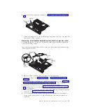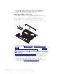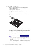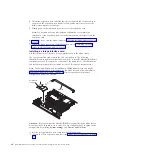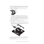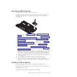
To install a DIMM, complete the following steps:
1.
Locate the DIMM connectors (see “Blade server connectors” on page 14).
Determine which DIMM connectors you will be installing memory into.
2.
If you are installing a DIMM in DIMM connectors ten through eighteen,
remove the front bezel (see “Removing the bezel assembly” on page 59).
3.
If a DIMM filler or another memory module is already installed in the DIMM
connectors, remove them (see “Removing a memory module” on page 63).
Note:
A DIMM or DIMM filler must occupy each DIMM socket before the
blade server is turned on.
4.
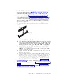
To install the DIMMs, repeat the following steps for each DIMM that you
install:
Retaining
clip
DIMM
a.
Make sure that the retaining clips are in the open position, away from the
center of the DIMM connector.
b.
Touch the static-protective package that contains the DIMM to any
unpainted
metal surface on the BladeCenter unit or any
unpainted
metal surface on any
other grounded rack component in the rack in which you are installing the
DIMM for at least two seconds; then, remove the DIMM from its package.
c.
Turn the DIMM so that the DIMM keys align correctly with the DIMM
connector on the system board.
Attention:
To avoid breaking the retaining clips or damaging the DIMM
connectors, handle the clips gently.
d.
Press the DIMM into the DIMM connector. The retaining clips will lock the
DIMM into the connector.
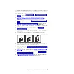
e.
Make sure that the small tabs on the retaining clips are in the notches on
the DIMM. If there is a gap between the DIMM and the retaining clips, the
DIMM has not been correctly installed. Press the DIMM firmly into the
connector, and then press the retaining clips toward the DIMM until the
tabs are fully seated. When the DIMM is correctly installed, the retaining
clips are parallel to the sides of the DIMM.
5.
If the front bezel has been removed, install it now (see “Installing the bezel
assembly” on page 60).
6.
Install the cover onto the blade server (see “Closing the blade server cover” on
page 56).
7.
Install the blade server into the BladeCenter unit (see “Installing the blade
server in a BladeCenter unit” on page 53).
Chapter 5. Removing and replacing blade server components
69
Содержание BladeCenter HS22V 7871
Страница 1: ...BladeCenter HS22V Type 7871 and 1949 Problem Determination and Service Guide...
Страница 2: ......
Страница 3: ...BladeCenter HS22V Type 7871 and 1949 Problem Determination and Service Guide...
Страница 16: ...xiv BladeCenter HS22V Type 7871 and 1949 Problem Determination and Service Guide...
Страница 20: ...4 BladeCenter HS22V Type 7871 and 1949 Problem Determination and Service Guide...
Страница 34: ...18 BladeCenter HS22V Type 7871 and 1949 Problem Determination and Service Guide...
Страница 64: ...48 BladeCenter HS22V Type 7871 and 1949 Problem Determination and Service Guide...
Страница 112: ...96 BladeCenter HS22V Type 7871 and 1949 Problem Determination and Service Guide...
Страница 240: ...224 BladeCenter HS22V Type 7871 and 1949 Problem Determination and Service Guide...
Страница 244: ...228 BladeCenter HS22V Type 7871 and 1949 Problem Determination and Service Guide...
Страница 252: ...236 BladeCenter HS22V Type 7871 and 1949 Problem Determination and Service Guide...
Страница 257: ......
Страница 258: ...Part Number 00Y8038 Printed in USA 1P P N 00Y8038...


