Installing options
71
9.
If you are installing a SCSI device, go to step 10.. If you are installing an IDE
device, go to step 11..
10. Install the two-drop SCSI cable:
a.
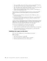
Locate the two-drop SCSI cable. The two-drop SCSI cable is located in the
bottom of the server between the open bays and the power supply area. It is
folded and restrained with a cable clamp.
b.
Connect one of the connectors on the two-drop SCSI cable to the back of the
drive. Go to step 12..
c.
Connect the other end of the two-drop SCSI cable to the SCSI connector on
the power backplane.
d. Go to step 12..
11. To install an IDE device, such as a CD-ROM or a DVD-ROM, use the two-drop
IDE cable that comes with the option.
a.
Remove the cable that connects the CD-ROM to the IDE connector on the
power backplane.
b.
Using the two-drop cable that came with the IDE option, connect the CD-
ROM and IDE device you are installing to the IDE connector on the power
backplane.
c.
Set the jumper on the back of the new IDE option as secondary.
12. Connect a power cable to the back of the drive. Power cables for removable-
media drives come installed in the server. The connectors are keyed and can be
inserted only one way.
13. If you are installing another 5.25-inch drive, do so now. Otherwise, continue with
step 14..
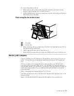
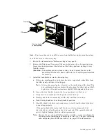
14. Connect the shuttle.
a.
Slide the shuttle back into the server
b.
Disengage the retaining levers from the notches on the chassis.
c.
Move the retaining levers toward the front of the server.
d. Secure the retaining levers in the horizontal position.
15. If you have other options to install or remove, do so now; otherwise, go to
“Completing the installation” on page 79.
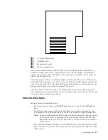
Installing memory-module kits
Before you continue with the memory-installation procedure, review the following:
•
Review the information in “Before you begin” on page 60.
•
All the DIMMs installed in each set must be the same size and speed, but all the
sets do not have to contain DIMMs of the same size and speed.
•
The memory board contains 16 DIMM connectors and supports 4-way memory
interleaving.
•
Install only 3.3 V, 168-pin, 8-byte, registered DIMMs. Only 100 MHz, 72-bit,
registered, synchronous, error correcting code (ECC), SDRAM configuration
DIMM memory is supported for the 128 MB, 256 MB, 512 MB and 1 GB (when
available) DIMMs.
•
If you install 4 GB of memory, some of the memory is reserved for system
resources. The amount reserved for system resources depends on the
configuration of the server.
Содержание 86655RY - Netfinity 7600 - 8665
Страница 1: ...IBM Hardware Maintenance Manual Netfinity 7600 Type 8665 Models 1RY 2RY ...
Страница 2: ......
Страница 3: ...IBM Hardware Maintenance Manual Netfinity 7600 Type 8665 Models 1RY 2RY ...
Страница 10: ...viii Hardware Maintenance Manual Netfinity 7600 Type 8665 Models 1RY 2RY ...
Страница 52: ...42 Hardware Maintenance Manual Netfinity 7600 Type 8665 Models 1RY 2RY ...
Страница 104: ...94 Hardware Maintenance Manual Netfinity 7600 Type 8665 Models 1RY 2RY ...
Страница 148: ...138 Hardware Maintenance Manual Netfinity 7600 Type 8665 Models 1RY 2RY ...
Страница 252: ...242 Hardware Maintenance Manual Netfinity 7600 Type 8665 Models 1RY 2RY ...
Страница 270: ...260 Hardware Maintenance Manual Netfinity 7600 Type 8665 Models 1RY 2RY ...
Страница 271: ...Related service information 261 ...
Страница 272: ...262 Hardware Maintenance Manual Netfinity 7600 Type 8665 Models 1RY 2RY ...
Страница 273: ...Related service information 263 ...
Страница 274: ...264 Hardware Maintenance Manual Netfinity 7600 Type 8665 Models 1RY 2RY ...
Страница 284: ...274 Hardware Maintenance Manual Netfinity 7600 Type 8665 Models 1RY 2RY ...
Страница 285: ...Related service information 275 ...
Страница 292: ...282 Hardware Maintenance Manual Netfinity 7600 Type 8665 Models 1RY 2RY ...
Страница 293: ......

