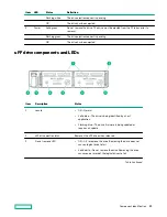
System board components
Item
Description
1
FlexibleLOM connector
2
Primary (processor 1) PCIe riser connector
3
System maintenance switch
4
Front display port/USB 2.0 connector
5
x4 SATA port 1
6
x4 SATA port 2
7
x2 SATA port 3
8
x1 SATA port 4
9
Front power/USB 3.0 connector
10
Optical/SATA port 5
11
Energy pack connector
12
microSD card slot
13
Chassis Intrusion Detection connector
14
Drive backplane power connector
15
Dual internal USB 3.0 connector
16
Type-a SmartArray connector
17
Secondary (processor 2) PCIe riser connector
18
System battery
19
TPM connector (optional)
20
Serial port connector (optional)
Component identification
18
Содержание HPE ProLiant DX360 Gen10
Страница 7: ...Regulatory information 183 Documentation feedback 184 Acronyms and abbreviations 185 7 ...
Страница 44: ...Operations 44 ...
Страница 74: ...8 Route and connect the data cable 9 Route and connect the power cable Hardware options installation 74 ...
Страница 101: ... Full length Hardware options installation 101 ...
Страница 107: ... 10 SFF SAS SATA NVMe Combo 4 LFF Hardware options installation 107 ...
Страница 125: ...8 Using a Torx T 10 screwdriver remove the Power UID USB assembly 8 SFF 4 LFF Hardware options installation 125 ...
Страница 129: ...6 Install the 4 LFF display port USB module 7 Route and connect the cable Hardware options installation 129 ...
Страница 150: ...2 SFF backplane to P816i a controller 10 SFF NVMe backplane to NVMe riser Cabling 150 ...
Страница 151: ...2 SFF NVMe backplane to primary riser 1 SFF rear backplane to system board SATA Cabling 151 ...


