CAUTION: If the TPM is removed from the original server and powered up on a different server, data stored in
the TPM including keys will be erased.
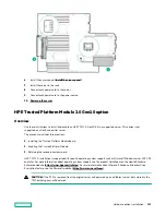
CAUTION: The TPM is keyed to install only in the orientation shown. Any attempt to install the TPM in a
different orientation might result in damage to the TPM or system board.
2. Align the TPM board with the key on the connector, and then install the TPM board. To seat the board, press the TPM
board firmly into the connector. To locate the TPM connector on the system board, see the server label on the access
panel.
3. Install the TPM cover:
a. Line up the tabs on the cover with the openings on either side of the TPM connector.
b. To snap the cover into place, firmly press straight down on the middle of the cover.
4. Proceed to Preparing the server for operation.
Hardware options installation
144
Содержание HPE ProLiant DX360 Gen10
Страница 7: ...Regulatory information 183 Documentation feedback 184 Acronyms and abbreviations 185 7 ...
Страница 44: ...Operations 44 ...
Страница 74: ...8 Route and connect the data cable 9 Route and connect the power cable Hardware options installation 74 ...
Страница 101: ... Full length Hardware options installation 101 ...
Страница 107: ... 10 SFF SAS SATA NVMe Combo 4 LFF Hardware options installation 107 ...
Страница 125: ...8 Using a Torx T 10 screwdriver remove the Power UID USB assembly 8 SFF 4 LFF Hardware options installation 125 ...
Страница 129: ...6 Install the 4 LFF display port USB module 7 Route and connect the cable Hardware options installation 129 ...
Страница 150: ...2 SFF backplane to P816i a controller 10 SFF NVMe backplane to NVMe riser Cabling 150 ...
Страница 151: ...2 SFF NVMe backplane to primary riser 1 SFF rear backplane to system board SATA Cabling 151 ...


