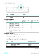
Item
Description
Status
3
Health LED
1
Solid green = Normal.
Flashing green = iLO is rebooting.
Flashing amber = System degraded.
Flashing red = System critical.
4
Power On/Standby button and
system power LED
1
Solid green = System on.
Flashing green = Performing power on sequence.
Solid amber = System in standby.
Off = No power present.
When all four LEDs described in this table flash simultaneously, a power fault has occurred.
To identify components in a degraded or critical state, see the Systems Insight Display LEDs, check iLO/BIOS logs, and reference the
server troubleshooting guide.
Facility power is not present, power cord is not attached, no power supplies are installed, power supply failure has occurred, or the
power button cable is disconnected.
UID button functionality
The UID button can be used to display the Server Health Summary when the server will not power on. For more
information, see the latest HPE iLO 5 User Guide on the
Hewlett Packard Enterprise website.
Front panel LED power fault codes
The following table provides a list of power fault codes, and the subsystems that are affected. Not all power faults are
used by all servers.
Subsystem
LED behavior
System board
1 flash
Processor
2 flashes
Memory
3 flashes
Riser board PCIe slots
4 flashes
FlexibleLOM
5 flashes
Storage controllers
6 flashes
System board PCIe slots
7 flashes
Power backplane or storage backplane
8 flashes
Power supply
9 flashes
Systems Insight Display LEDs
The Systems Insight Display LEDs represent the system board layout. The display enables diagnosis with the access panel
installed.
Component identification
12
Содержание HPE ProLiant DX360 Gen10
Страница 7: ...Regulatory information 183 Documentation feedback 184 Acronyms and abbreviations 185 7 ...
Страница 44: ...Operations 44 ...
Страница 74: ...8 Route and connect the data cable 9 Route and connect the power cable Hardware options installation 74 ...
Страница 101: ... Full length Hardware options installation 101 ...
Страница 107: ... 10 SFF SAS SATA NVMe Combo 4 LFF Hardware options installation 107 ...
Страница 125: ...8 Using a Torx T 10 screwdriver remove the Power UID USB assembly 8 SFF 4 LFF Hardware options installation 125 ...
Страница 129: ...6 Install the 4 LFF display port USB module 7 Route and connect the cable Hardware options installation 129 ...
Страница 150: ...2 SFF backplane to P816i a controller 10 SFF NVMe backplane to NVMe riser Cabling 150 ...
Страница 151: ...2 SFF NVMe backplane to primary riser 1 SFF rear backplane to system board SATA Cabling 151 ...


