4.
Remove all power:
a. Disconnect each power cord from the power source.
b. Disconnect each power cord from the server.
5.
Do one of the following:
a. Extend the server from the rack.
b. Remove the server from the rack.
6.
7.
Install the controller.
8.
Connect the cables.
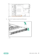
The following illustration shows the 8+2 SFF backplane configuration connected to the controller.
Hardware options installation
113
Содержание HPE ProLiant DX360 Gen10
Страница 7: ...Regulatory information 183 Documentation feedback 184 Acronyms and abbreviations 185 7 ...
Страница 44: ...Operations 44 ...
Страница 74: ...8 Route and connect the data cable 9 Route and connect the power cable Hardware options installation 74 ...
Страница 101: ... Full length Hardware options installation 101 ...
Страница 107: ... 10 SFF SAS SATA NVMe Combo 4 LFF Hardware options installation 107 ...
Страница 125: ...8 Using a Torx T 10 screwdriver remove the Power UID USB assembly 8 SFF 4 LFF Hardware options installation 125 ...
Страница 129: ...6 Install the 4 LFF display port USB module 7 Route and connect the cable Hardware options installation 129 ...
Страница 150: ...2 SFF backplane to P816i a controller 10 SFF NVMe backplane to NVMe riser Cabling 150 ...
Страница 151: ...2 SFF NVMe backplane to primary riser 1 SFF rear backplane to system board SATA Cabling 151 ...


