19
for the frequency inverter to have good driving performance and operating efficiency, the frequency inverter must
obtain the preparation parameters of the controlled motor.
Motor 1 parameter
Parameter description
Description
F1-01 F1-05
Rated power / voltage / current / frequency / speed of
motor
Model parameters, manual
input
F1-06 F1-20
Equivalent stator resistance, inductance, rotor
inductance, etc. inside the motor
Tuning parameter
Methods for obtaining the internal electrical parameters of the controlled motor by the frequency inverter include
dynamic identification, static identification, manual input of motor parameters, etc.
Identification method
Application
Identification effect
No - load dynamic
identification
Suitable for asynchronous motors. Occasions where the
motor and the application system are conveniently
separated
Best
On - load dynamic
identification
Suitable for asynchronous motors. Where the motor is
not easily separated from the application system
May
Static identification
It is only suitable for asynchronous motors, where it is
difficult to separate the motor from the load and dynamic
identification of operation is not allowed
Poor
Manually
enter
parameters
It is only suitable for asynchronous motors. When the
motor is difficult to separate from the application system,
the parameters of the same type of electric machine
successfully identified by the frequency inverter are
copied and input into the corresponding function codes
of F1-00
~
F1-10
May
Automatic tuning of motor parameters (motor self - learning) steps are as follows:
The following explains the parameter identification method of the default motor 1 as an example. The
identification method of the motor 2 is the same as that of the default motor 1, except that the function code number
needs to be changed in a targeted way:
If the motor can be completely disconnected from the load, under the condition of power failure, the motor
can be mechanically separated from the load so that the motor can rotate freely without load.
After power on, first select the frequency inverter command source (F0 - 02) as the operation panel
command channel.
Accurately input the nameplate parameters of the motor (for example, F1-00
~
F1-05). Please input the
parameters of the lower surface according to the actual parameters of the motor (according to the current
motor selection)
If it is an asynchronous motor, then F1 - 29 (tuning selection, for motor 2, it should be FB- 29 function code)
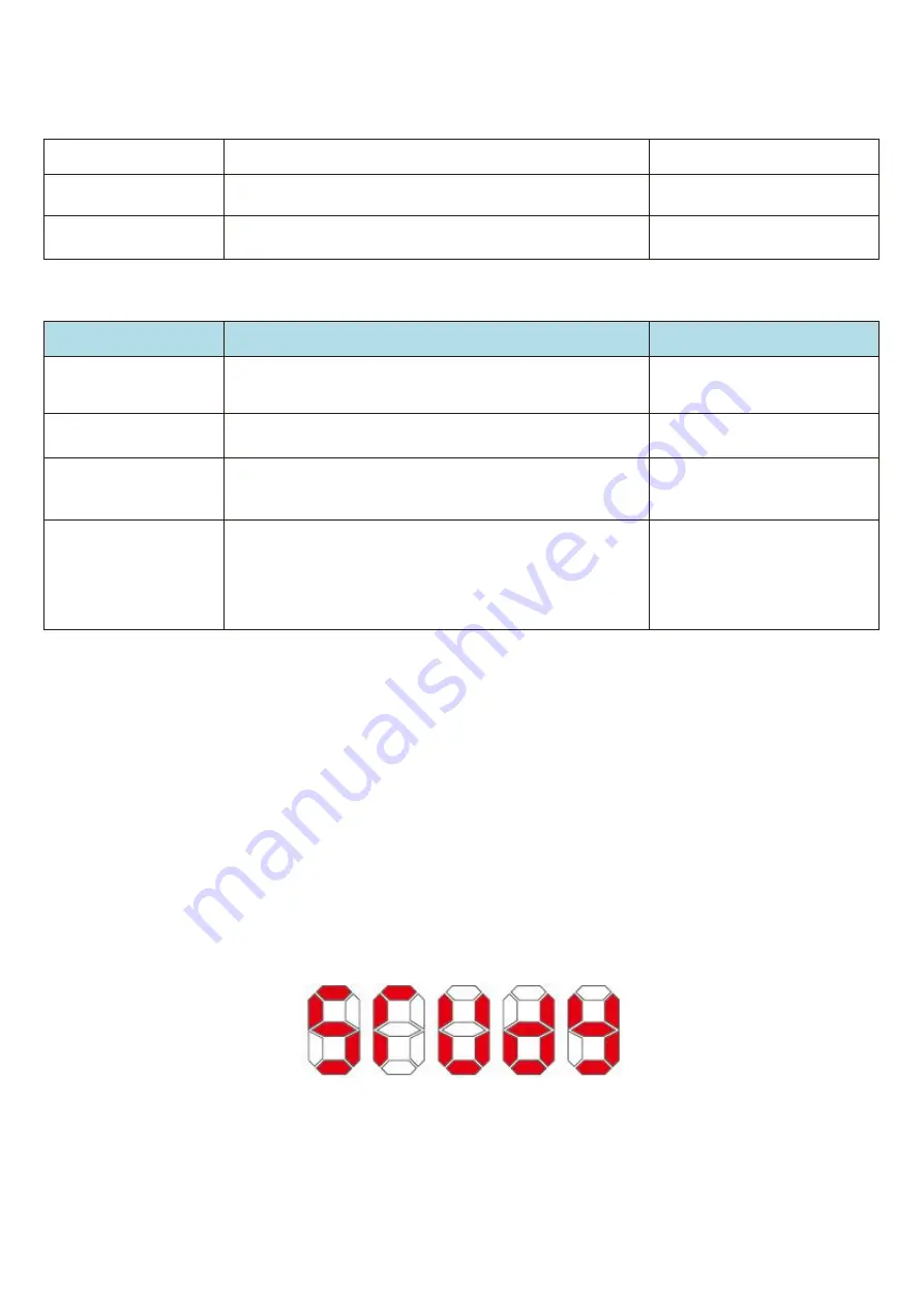
please select 2 (asynchronous motor fully tuned), press enter to confirm, at this point, the keyboard shows
STUDY, as shown in the following figure:
Then press the run key on the panel, the frequency inverter will drive the motor to accelerate and decelerate,
rotate forward and backward, the operation indicator light will illuminate, and the operation duration will be
recognized for about 2 minutes. When the above display information disappears, the normal parameter display state
will be returned, indicating that the tuning is completed. After the complete tuning, the frequency inverter will
automatically calculate the following parameters of the motor:
F1 - 06: Asynchronous motor stator resistance
F1 - 07: Asynchronous motor rotor resistance
Содержание HV480 Series
Страница 1: ...HV610 Series Frequency Inverter User Manual HNC Electric Limited ...
Страница 12: ...8 2 2 3 Frequency inverter control loop terminal description ...
Страница 13: ...9 ...
Страница 166: ...162 Appendix II Plastic shell dimensions and mounting dimensions Fig 1 R75G3 2R2G3 Fig 2 004G3 7R5G3 ...
Страница 167: ...163 Appendix III dimensions and mounting dimensions of sheet metal machines Fig 3 011G3 200G3 Fig 4 185G3 560G3 ...


