2 Inbetriebnahme
2 Putting Into Operation
Elektronische Last Serie PLI - Electronic Load PLI Series
49 / 323
4. Last-Kabel entsprechend Abbildung 2.21 mit den
mitgelieferten Schrauben M10x30 an die Stromschienen
anschließen.
4. Connect load cables to the copper bars corresponding to Figure
Halten Sie die Schrauben- und Scheibenanordnung in Abbildung
2.13 ein, um die entsprechenden Sicherheitsabstände zu
gewährleisten!
Follow the assembly order of the screws and washers in Figure 2.13
to meet the specifications for the electric safety distances!
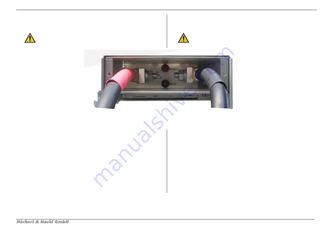
Abbildung 2.21: Sicherheitsabdeckung für Geräte ab 5 HE mit angeschlossenen Last-Kabeln
Figure 2.21: Safety cover for devices with 5 HE or more with connected load cables
5. Demontierte Abdeckung von hinten über die Last-Kabel und
über den Anschlussblock stülpen. Abdeckung mit den
mitgelieferten Torxschrauben FTM4x8 an der Rückwand
verschrauben.
5. Put the demounted cover from the rear side over the load lines
and the connector block. Screw the cover to the rear panel using
the supplied torx screws FTM4x8 coming with the cover.
6. Abdeckschieber wie in Abbildung 2.22 an der Rückseite der
Abdeckung montieren, so dass diese die Kabel so eng wie
möglich umschließen.
6. Mount the sliders at the cover’s rear side in a way that the cables
are surrounded as closely as possible. See Figure 2.22
7. Gehäuse an der Schraube am linken Seitenteil der
Sicherheitsabdeckung wie in Abbildung 2.23 mit der Schutzerde
des Gesamtsystems verbinden.
Dazu eine Schutzleiter-Anschlussleitung von mindestens 4 mm²
(AWG11) verwenden.
7. Connect the screw on the left part of the safety cover with
Protective Earth potential of the complete system, as it is shown in
Figure 2.23.
Use a Protective Earth wire with at least 4 mm² (AWG11) cross-
section.


