


78
Maintenance
9.4.2 Working with Wiring Connectors
All inter-connect wiring plugs and receptacles are mechanically polarized to assist in proper
insertion. Always note where a connector belongs and what orientation it was in prior to removal.
This will assure that you get it back in the right place during reassembly.
Locations and descriptions of each fuse and connector on the Base Board and CPU
board are shown in
and
.
9.5 Replacing the Internal Desiccant Module
The Internal Desiccant Module (P/N 787) consists of a moisture absorbing material inside
a poly bag. The module should be replaced if the Internal Case Humidity Indicator on the
front panel turns pink.
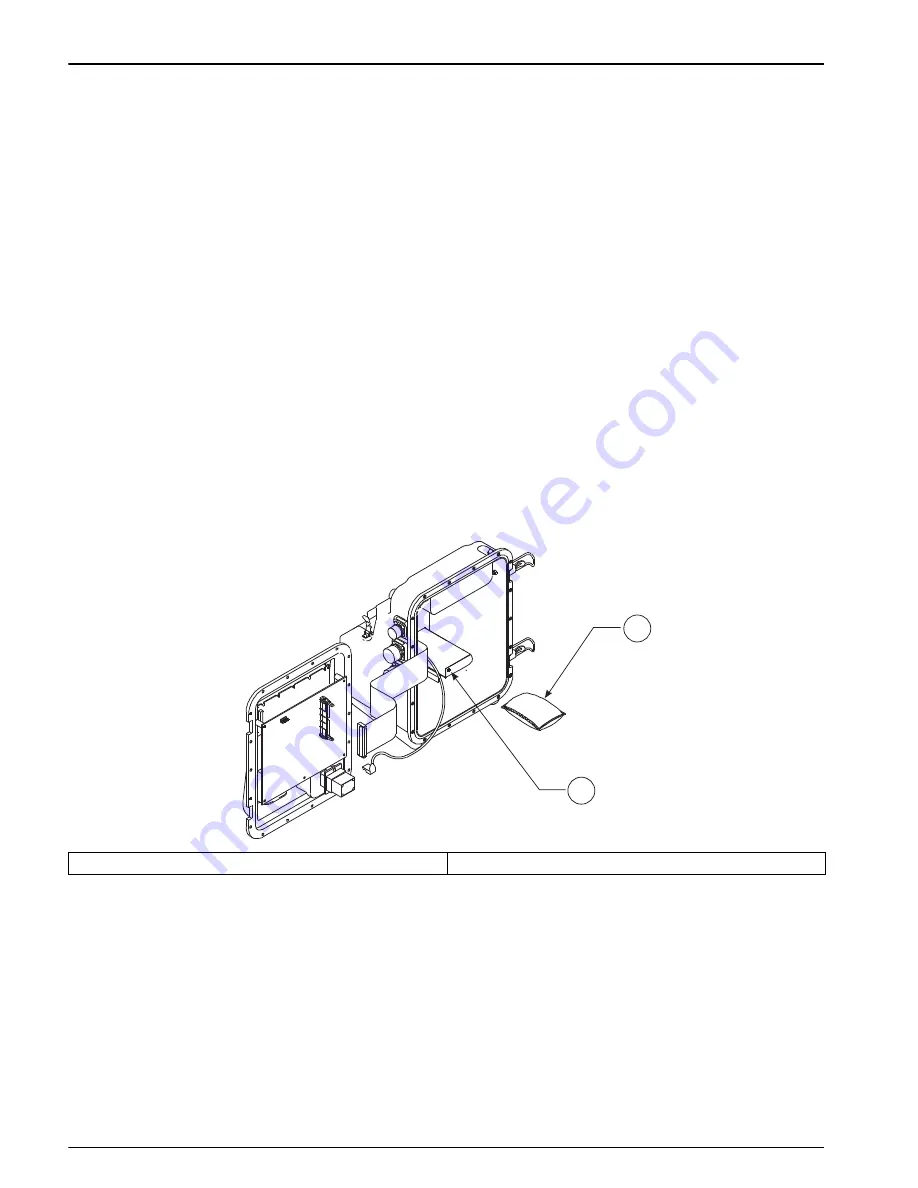
To replace the desiccant module, proceed as follows:
1.
Remove the screw holding the desiccant door in place and remove the door
(
2.
Slide out the old desiccant module and slide in a fresh one
3.
Reattach the desiccant door.
The desiccant module cannot be recharged by heating. Do not attempt to bake the
desiccant module in an oven to remove the moisture because this could be a fire hazard.
Figure 21 Replacing Internal Desiccant Module
9.6 Replacing the Internal Case-Humidity Indicator Disc
After replacing the desiccant module and re-sealing the case, the Internal Case Humidity
Indicator Disc (P/N 2660) will return to its original blue color within 24 hours.
If the indicator disc fails to return to blue after replacing the desiccant module, replace the
disc. The indicator disc is held in place by a small clip and screw. To gain access to the
indicator disc you must first remove the CPU board. Be sure to observe proper handling
for static sensitive CMOS devices.
1
Internal Module (P/N 787)
2
Remove desiccant access screw and door.
2
1
Содержание Sigma 950
Страница 2: ......
Страница 6: ...4...
Страница 20: ...18 Introduction...
Страница 34: ...32 Basic Programming Setup...
Страница 50: ...48 Sensor Installation...
Страница 82: ...80 Maintenance...
Страница 83: ...81 Appendix A Program Flow Charts Figure 22 Overview of Basic Program Menus...
Страница 84: ...82 Program Flow Charts Figure 23 Setup Flow Chart...
Страница 85: ...83 Program Flow Charts Figure 24 Options Flow Chart...
Страница 86: ...84 Program Flow Charts Figure 25 Alarms Menus Flow Chart...
Страница 87: ...85 Program Flow Charts Figure 26 Calibration Menus Flow Chart Page 1...
Страница 88: ...86 Program Flow Charts...
Страница 102: ...100 Programming Features...
Страница 106: ...104 Primary Devices Head Measurement Locations...
Страница 126: ...124 SCADA Modbus System Guidelines...


