


17
General operating notices
Charging with automatic chargers
To achieve quicker recharging of the single cell LiIo
battery, Graupner automatic chargers can also be
used. The table below shows a selection of these
chargers.
Recommended chargers (accessory)
Order
No.
Designation
Input v
oltage 220
V
Input v
oltage 12
V
suitable for
battery types
integ
r.
balancer
NiCd
NiMH
LiP
o/LiIo
lead batter
y
6411
Ultramat 8
x
x
x
x
x
6463
Ultramat 12 plus
x
x
x
x
x
x
6464
Ultramat 14 plus
x
x
x
x
x
x
x
6466
Ultra Trio plus 14
x
x
x
x
x
x
x
6468
Ultramat 16S
x
x
x
x
x
x
x
6469
Ultra Trio Plus 16
x
x
x
x
x
x
6470
Ultramat 18
x
x
x
x
x
x
x
6475
Ultra Duo Plus 45
x
x
x
x
x
x
x
6478
Ultra Duo Plus 60
x
x
x
x
x
x
x
6480
Ultra Duo Plus 80
x
x
x
x
x
x
x
Charger cable, order no.
3022
is additionally needed for the
transmitter and charger cable, order no.
3021
is additionally
needed for the receiver.
Other charger units and details about the listed chargers can
be found in the Graupner RC main catalog or in Internet at
www.graupner.de.
The charger socket is equipped standard with a
diode to protect against reversed polarity. Original
Graupner automatic chargers also detect battery
voltage polarity.
Observe the confi guration notices for the charger
used.
First connect the charger cable's banana
plugs to the charger and only then connect
the cable's other end into the charging jack
on the transmitter. Never allow the bare ends
of the banana plugs to come into contact with
one another when the other end of the cable is
plugged into the transmitter.
Charging current may not exceed 1.5 A as
otherwise the diode, and perhaps other
components, could be damaged. If necessary,
limit the current at the charger.
mc-20
HoTT charging jack polarity
The charger cables on the market from other
manufacturers often have different polarities.
Therefore use only an original
Graupner
charger
cable, order no.
3022
.
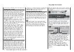
Removing the transmitter's battery
To remove the transmitter's battery, fi rst unlatch the
cover of the battery compartment on the rear side of
the transmitter housing then remove the cover.
Take out the transmitter's battery then disconnect the
transmitter battery's connector by carefully pulling on
the supply line cable.
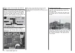
Inserting the transmitter's battery
The battery connector is protected against a
reverse polarity connection by two slanted edges,
see illustration. When correctly plugged in, the
unconnected pin of the connector is at the bottom,
as shown in the illustration. The plus
pole (red lead) is in the middle and
the minus pole (brown or black lead)
is toward the antenna side.
Never try to force the connector
onto its circuit-board socket.
Place the battery into its
compartment and close the transmitter's cover.
Transmitter
connector polarity
Battery connector
Battery connector
Содержание 32032
Страница 1: ...33020 mc 20HoTT 2 en Programming Manual o Pro Pro mc 20 mc 20...
Страница 15: ...15 For your notes...
Страница 21: ......
Страница 27: ...27 For your notes...
Страница 41: ...41 For your notes...
Страница 53: ...53 For your notes...
Страница 59: ...59 For your notes...
Страница 63: ...63 For your notes...
Страница 93: ...93 For your notes...
Страница 97: ...97 For your notes...
Страница 141: ...141 How is a ight phase programmed...
Страница 145: ...145 For your notes...
Страница 155: ...155 For your notes...
Страница 175: ...175 For your notes...
Страница 203: ...203 For your notes...
Страница 219: ...219 For your notes...
Страница 253: ...253 For your notes...
Страница 283: ...283 For your notes...
Страница 321: ...321 For your notes...
Страница 322: ...322 For your notes...
Страница 323: ...323 For your notes...