161
Detail program description - Wing mixers
controls the fl ap position of the ailerons via the
percentage value entered in the "Ail" (and "Ail2")
column on the "FLAP" line of the multi-fl ap menu.
However, in order to improve control sensitivity
for fl ap settings, travel should be reduced to
about 25 % in "Input 6" line of the »
Control
adjust
« menu.
c) … alternatively, you can also leave the default
entry of "0 %" in the "AILE" (and "AIL2") column
on the "FLAP" line of the multi-fl ap menu, and
use the »
Control adjust
« menu to assign both
input 6 and input 5 to the
same
transmitter
control. You can then set the degree to which
both fl ap pairs are affected, optionally making
this fl ight phase-dependent by selecting "PH"
in the "Type" column, with the respective travel
adjustment.
Basic programming procedure
Select the desired line with the
1.
cd
selection keys
of the left or right touch pad.
Depending on the line selected, the bottom line of
the display will either show the "Next page" icon
(
) or a switch icon.
Depending on the line selected, you will either
2.
switch to the next page – on which you carry out
the same procedure as below – or the desired
value fi eld is activated by tapping the center
SET
key of the right touch pad.
Use the selection keys to set the mixer ratio or
3.
degree of differential.
To confi gure symmetrical mixer values, move the
transmitter control or joystick to its center position,
so that the marker frame surrounds both value
fi elds. To confi gure asymmetric values, move the
transmitter control/joystick to the corresponding side.
Negative and positive parameter values are
possible, in order to be able to adjust the
respective function to the direction of servo
any mixers on the "Brake settings" sub-menu.
Otherwise, the mixer travel is expanded back to
100 % automatically.
All other mixers in the »
Wing mixers
« menu have
their neutral point with the control at its center, i.e.
they have no effect at this control position. The value
set is mixed in at full travel.
Mixer functions
The individual options in the »
Wing mixers
« menu
are discussed below, separately for single-, dual-
and multi-fl ap models. Before we start, a number of
remarks on the differentials for ailerons and fl aps:
Aileron differential
Aileron differential
Brake settings
0%
Aileron
0%
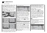
W I N G M I X E R S
Elevator
aileron
0%
0%
–––
–––
rudder
2
3
4
5
Normal
Fl-Pos.
Diff.
Ail-tr
AI
Normal
AILE
+100%
WK2
FLAP
0%
0%
0%
+100%
0%
+100%
0%
+100%
0%
0%
0%
0%
+100%
0%
0%
0%
FL
+100%
0% +100%
For aerodynamic reasons, the drag generated on
an aileron oriented downwards is greater than that
generated by the same aileron when it is oriented
upwards by the same amount. One effect of this
unequal distribution of drag produces is a yawing
motion around the vertical axis and, accordingly, a
"turning away" from the intended direction of fl ight,
which is why this undesirable side effect is also
rotation or fl ap orientation.
A simultaneous tap on the
4.
cd
or
ef
keys of the
right touch pad (
CLEAR
) will reset the entry value
in the given active (inverse video) fi eld back to its
default value.
Complete the entry with a tap on the center
5.
ESC
key of the left touch pad or the center
SET
key of
the right touch pad.
Assigning switches
Wing mixers "Aileron 2
¼
4 rudder" and "Flaps 6
¼
3 elevator" can be made optionally on/off switchable
by way of a switch or expanded switch. Accordingly,
when the respective line is selected, the familiar
switch symbol (
) will appear on the lower edge of
the screen.
Switching delays
The delay time or switch time confi gured on
the »
Phase settings
« menu, page 142, for the
respective fl ight phase also affects all wing mixers
and thus avoids abrupt changes to fl ap confi gurations
when switching between the fl ight phases.
Mixer neutral points
(Offset)
For all mixers on the "Brake settings" sub-menu, the
"brake offset" to be set on the »
Model type
« menu is
to be confi gured to the transmitter control position at
which the airbrakes are retracted.
Accordingly, in the "Brake offset" line of the »
Model
type
« menu, see page 94, specify Input 1, 7, 8 or
9 and the offset to accommodate personal piloting
habits. When selecting "input 1", please note also
that you may need to specify your desired "Throttle
min" position "forward/back" before establishing the
offset point in the "Motor at C1" line.
Note:
If the offset is not set right at the end of the
transmitter travel, the rest of the travel is a "dead
zone", i.e. the transmitter control does not infl uence
Содержание 32032
Страница 1: ...33020 mc 20HoTT 2 en Programming Manual o Pro Pro mc 20 mc 20...
Страница 15: ...15 For your notes...
Страница 21: ......
Страница 27: ...27 For your notes...
Страница 41: ...41 For your notes...
Страница 53: ...53 For your notes...
Страница 59: ...59 For your notes...
Страница 63: ...63 For your notes...
Страница 93: ...93 For your notes...
Страница 97: ...97 For your notes...
Страница 141: ...141 How is a ight phase programmed...
Страница 145: ...145 For your notes...
Страница 155: ...155 For your notes...
Страница 175: ...175 For your notes...
Страница 203: ...203 For your notes...
Страница 219: ...219 For your notes...
Страница 253: ...253 For your notes...
Страница 283: ...283 For your notes...
Страница 321: ...321 For your notes...
Страница 322: ...322 For your notes...
Страница 323: ...323 For your notes...


