300
BBC HLG Look-Up Table
Scene-Light versus Display-Light Conversions
code value 940) (required for ITU-R BT.814 HDR PLUGE and ITU-R BT.2111 HDR Color Bars),
so are most suitable for broadcast TV applications.
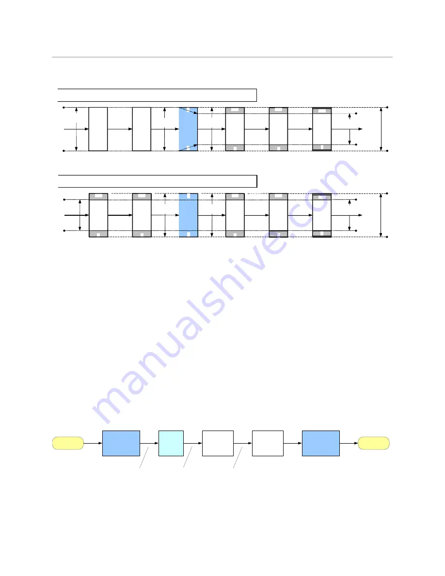
Fig. A-1: Type II signal scaling, intended for full-range input signals (for example, S-Log3)
Fig. A-2: Type III signal scaling, primarily intended for hardware-based LUT applications
The Type II “full-range mode” LUT is used to convert full-range PQ and S-Log3 signals to
HLG. So full-range Type II versions of the PQ1000, PQ4000, S-Log3 (100%) and S-Log3
(200%) conversion LUTs are provided.
We recommended only using narrow-range signals with HLG, to improve interoperability,
maintain signal fidelity and reduce the likelihood of errors in production. So even when a
hardware LUT device is operated in full-range mode, the HLG output signal is always offset
and scaled within the full-range “container”, to lie within the usual narrow signal range of 64
to 940 (10-bits).
Scene-Light versus Display-Light Conversions
Most SDR/HDR format conversions are based on “display-light”. By that we mean that the
conversion calculates the light produced by the original signal on a reference display
operating in the original format, and attempts to produce a similar light output on a
reference display operating in the new output format. Display-light conversions are
designed to preserve the artistic intent of the pictures after conversion. So display-light
conversions work well for graded content. An example of a display-light conversion for
BT.709 to BT.2100 HLG is shown in the Figure below.
Fig. A-3: SDR to HDR Display-Light Conversion
For live production, however, it is usually more important to color match signals produced
in different formats – for example a native BT.2100 HLG camera with an SDR BT.709 super
3D-LUT
Matrix
1023
0
Y
'
C
'
B
C
'
R
Input Signal Range:
Full
LUT Mode:
Full
1023
0
R
'
G
'
B
'
0
1
940
64
Matrix
1023
0
R
'
G
'
B
'
940
64
1023
0
Y
'
C
'
B
C
'
R
Scale Output
(0 - 1023)
Output Signal Range:
Narrow
940
64
1019
4
Clip to SDI
Range
Y
'
C
'
B
C
'
R
Type II
Normalisation
(0 - 1)
Input
Input signal and
processing range
Output
Nominal output
signal range
Processing
range
3D-LUT
940
64
Matrix
1023
0
Y
'
C
'
B
C
'
R
Input Signal Range:
Narrow
LUT Mode:
Full
940
64
1023
0
R
'
G
'
B
'
0
1
940
64
Matrix
1023
0
R
'
G
'
B
'
940
64
1023
0
Y
'
C
'
B
C
'
R
Output Signal Range:
Narrow
Input
940
64
1019
4
Clip to
SDI Range
Y
'
C
'
B
C
'
R
Type III
Scale Output
(0 - 1023)
Normalisation
(0 - 1)
Nominal input
signal range
Output
Nominal output
signal range
Processing
range
SDR BT.709
signal
BT.1886 EOTF
L
W
=100 cd/m
2
BT.709
to BT.2020
Colour
SDR BT.709
display‐light
Optional
brightness
adjustment
Inverse HLG
EOTF
L
W
=1000 cd/m
2
HDR display‐light
HDR BT.2100
HLG signal
SDR BT.2020
display‐light
Optional
highlight
expansion
Содержание XIP-3901
Страница 1: ...XIP 3901 AGILE SDI IP PROCESSING PLATFORM User Manual 13 03065 010 AL M00 2021 08 04 ...
Страница 16: ...16 Table of Contents ...
Страница 18: ...18 Introduction to the XIP 3901 Agile SDI IP Processing Platform ...
Страница 60: ...60 Local Control Using the Densité Frame Control Panel Setting the Card s IP Addresses ...
Страница 65: ...65 XIP 3901 User Manual The iControl panel for the card then shown ...
Страница 113: ...113 XIP 3901 User Manual Figure 7 25 Options Panel Shown on XIP 3901 UC ...
Страница 114: ...114 Configuring the XIP 3901 UC DC FS Applications with iControl Options Panel ...
Страница 152: ...152 Configuring the XIP 3901 UDC IP v1 2 Application with iControl Metadata Panel Figure 8 21 Metadata panel ...
Страница 168: ...168 Configuring the XIP 3901 UDC IP v1 2 Application with iControl Options Panel ...
Страница 190: ...190 Configuring the XIP 3901 UDC IF v3 0 Application with iControl UDC1 UDC2 Tab Figure 9 14 HDR UDC1 UDC2 Tab ...
Страница 198: ...198 Configuring the XIP 3901 UDC IF v3 0 Application with iControl Metadata Panel Figure 9 16 Metadata panel ...
Страница 202: ...202 Configuring the XIP 3901 UDC IF v3 0 Application with iControl Inputs Tab Figure 9 18 Audio Inputs Tab ...
Страница 280: ...280 Configuring the XIP 3901 JPEG XS v1 0 Application with its Web Interface Technical Support Panel ...
Страница 290: ...290 Maintenance Troubleshooting Keep Fiber Connections Clean ...
Страница 298: ...298 Installing the SFP Ethernet Module Removing the SFP module ...
Страница 307: ...307 XIP 3901 User Manual ...


