CHAPTER 5: SETTINGS
GROUPED ELEMENTS
L90 LINE CURRENT DIFFERENTIAL SYSTEM – INSTRUCTION MANUAL
5-249
5
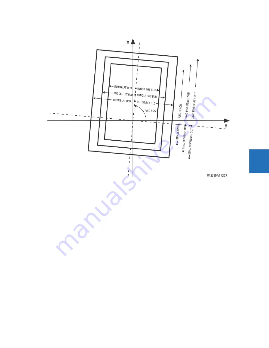
Figure 5-134: Power swing detect quadrilateral operating characteristics
The FlexLogic output operands for the power swing detect element are as follows:
•
POWER SWING OUTER
,
POWER SWING MIDDLE
,
POWER SWING INNER
,
POWER SWING TMR2 PKP
,
POWER SWING TMR3 PKP
, and
POWER SWING TMR4 PKP
are auxiliary operands that facilitate testing and special applications
•
POWER SWING BLOCK
blocks selected protection elements, such as distance functions
•
POWER SWING UN/BLOCK
blocks those protection elements that are intended to be blocked under power swings, but
subsequently unblocked when a fault occurs after the power swing blocking condition has been established
•
POWER SWING 50DD
indicates that an adaptive disturbance detector integrated with the element has picked up. This
operand triggers on faults occurring during power swing conditions. This includes both three-phase and single-pole-
open conditions.
•
POWER SWING INCOMING
indicates an unstable power swing with an incoming locus (the locus enters the inner
characteristic)
•
POWER SWING OUTGOING
indicates an unstable power swing with an outgoing locus (the locus leaving the outer
characteristic). This operand can be used to count unstable swings and take certain action only after a pre-defined
number of unstable power swings.
•
POWER SWING TRIP
is a trip command
The settings for the power swing detect element are as follows.
POWER SWING FUNCTION
— This setting enables and disables the power swing detection element. The setting applies to
both power swing blocking and out-of-step tripping functions.
POWER SWING SOURCE
— The source setting identifies the signal source for both blocking and tripping functions.
POWER SWING SHAPE
— This setting selects the shapes (either “Mho” or “Quad”) of the outer, middle, and inner
characteristics of the power swing detect element. The operating principle is not affected. The “Mho” characteristics use
the left and right blinders.
Содержание L90
Страница 14: ...1 4 L90 LINE CURRENT DIFFERENTIAL SYSTEM INSTRUCTION MANUAL FOR FURTHER ASSISTANCE CHAPTER 1 INTRODUCTION 1 ...
Страница 68: ...2 54 L90 LINE CURRENT DIFFERENTIAL SYSTEM INSTRUCTION MANUAL SPECIFICATIONS CHAPTER 2 PRODUCT DESCRIPTION 2 ...
Страница 136: ...3 68 L90 LINE CURRENT DIFFERENTIAL SYSTEM INSTRUCTION MANUAL CONNECT TO D400 GATEWAY CHAPTER 3 INSTALLATION 3 ...
Страница 224: ...4 88 L90 LINE CURRENT DIFFERENTIAL SYSTEM INSTRUCTION MANUAL FLEXLOGIC DESIGN USING ENGINEER CHAPTER 4 INTERFACES 4 ...
Страница 692: ...6 36 L90 LINE CURRENT DIFFERENTIAL SYSTEM INSTRUCTION MANUAL PRODUCT INFORMATION CHAPTER 6 ACTUAL VALUES 6 ...
Страница 708: ...7 16 L90 LINE CURRENT DIFFERENTIAL SYSTEM INSTRUCTION MANUAL TARGETS MENU CHAPTER 7 COMMANDS AND TARGETS 7 ...
Страница 742: ...9 6 L90 LINE CURRENT DIFFERENTIAL SYSTEM INSTRUCTION MANUAL TESTING CHAPTER 9 COMMISSIONING 9 ...
Страница 804: ...10 62 L90 LINE CURRENT DIFFERENTIAL SYSTEM INSTRUCTION MANUAL FAULT LOCATOR CHAPTER 10 THEORY OF OPERATION 10 ...
Страница 872: ...C 6 L90 LINE CURRENT DIFFERENTIAL SYSTEM INSTRUCTION MANUAL COMMAND LINE INTERFACE APPENDIX C COMMAND LINE INTERFACE C ...
Страница 878: ...D 6 L90 LINE CURRENT DIFFERENTIAL SYSTEM INSTRUCTION MANUAL REVISION HISTORY APPENDIX D MISCELLANEOUS D ...
Страница 882: ...iv L90 LINE CURRENT DIFFERENTIAL SYSTEM INSTRUCTION MANUAL ABBREVIATIONS ...
Страница 900: ...xviii L90 LINE CURRENT DIFFERENTIAL SYSTEM INSTRUCTION MANUAL INDEX ...


