CHAPTER 4: INTERFACES
FRONT PANEL INTERFACE
L60 LINE PHASE COMPARISON SYSTEM – INSTRUCTION MANUAL
4-49
4
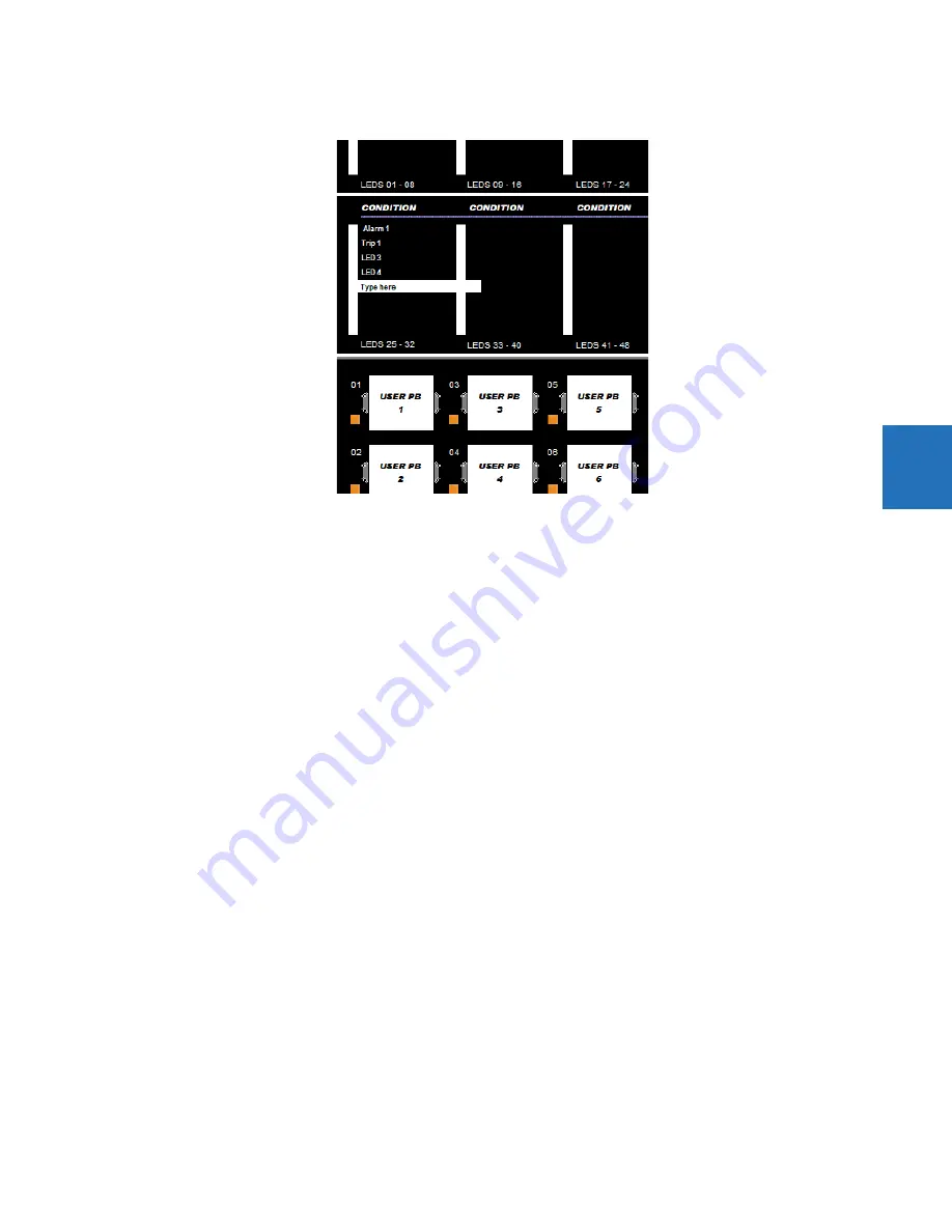
Figure 4-53: Standard front panel label designer (LEDs shown)
4.
Optionally save the changes by clicking the
Save
icon on the toolbar.
5.
Click the
icon on the toolbar. Consider printing to PDF format and adjusting the zoom for appropriate label size,
then print on a physical printer.
6.
Cut labels as a block or individually, for example with scissors or an Exacto knife.
7.
If there is a plastic cover over the front panel, remove it by gently pushing in on the right side and lifting off the cover.
8.
Remove the plastic cover over the LEDs or pushbutton(s) using a screw driver.
9.
Insert the labels.
10. Re-attach the plastic covers.
4.2.5.3 Graphical front panel
The L60 includes software for labelling the LEDs and pushbuttons on the graphical front panel and a sticker sheet with pre-
printed and blank labels. The pre-printed labels are on the top-left of the template sheet, and the blank labels are on the
bottom-right. Use the pre-printed labels, or use the designer provided in the software and print labels onto the template.
One sheet is provided.
The example shows LED labeling, wjth pushbutton labeling below it (cut off).
To create LED and pushbutton labels for the front panel:
1.
In the EnerVista software, in the Online or Offline Window area, access
Settings > Front Panel Label Designer
or
Front Panel Label Designer
(at the product root level). The designer window opens with pre-configured labels.
2.
Under
File > Print Setup
, change the page orientation to
Landscape
.
3.
In the label designer window, delete all labels not wanted for printing. This can be done by clicking the
Reset
button to
clear all labels, or by selecting each unwanted label and deleting it. Otherwise, all labels displayed print on the
template and use up the template. If you make a mistake, exit the window and open it again to view the default labels.
4.
Based on the location on the template on which to print, create the labels by typing in the appropriate slots.
Содержание L60
Страница 10: ...x L60 LINE PHASE COMPARISON SYSTEM INSTRUCTION MANUAL TABLE OF CONTENTS ...
Страница 14: ...1 4 L60 LINE PHASE COMPARISON SYSTEM INSTRUCTION MANUAL FOR FURTHER ASSISTANCE CHAPTER 1 INTRODUCTION 1 ...
Страница 122: ...3 72 L60 LINE PHASE COMPARISON SYSTEM INSTRUCTION MANUAL CONNECT TO D400 GATEWAY CHAPTER 3 INSTALLATION 3 ...
Страница 590: ...5 382 L60 LINE PHASE COMPARISON SYSTEM INSTRUCTION MANUAL TESTING CHAPTER 5 SETTINGS 5 ...
Страница 632: ...7 12 L60 LINE PHASE COMPARISON SYSTEM INSTRUCTION MANUAL TARGETS MENU CHAPTER 7 COMMANDS AND TARGETS 7 ...
Страница 736: ...A 14 L60 LINE PHASE COMPARISON SYSTEM INSTRUCTION MANUAL FLEXANALOG ITEMS APPENDIX A FLEXANALOG OPERANDS A ...
Страница 744: ...C 6 L60 LINE PHASE COMPARISON SYSTEM INSTRUCTION MANUAL COMMAND LINE INTERFACE APPENDIX C COMMAND LINE INTERFACE C ...
Страница 752: ...iv L60 LINE PHASE COMPARISON SYSTEM INSTRUCTION MANUAL ABBREVIATIONS ...


